|
Last Modified: 4-30-2014 |
6.6 J |
Doc ID: RM000000WIO006X |
|
Model Year: 2006 |
Model: LX470 |
Prod Date Range: [05/2005 -
] |
|
Title: CAN COMMUNICATION: CAN COMMUNICATION SYSTEM: CAN Bus Line; 2006 MY LX470 [05/2005 - ] |
DESCRIPTION
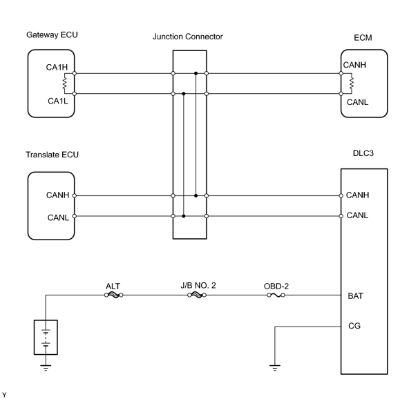
When any DTC for the CAN communication system is output, first measure the resistance between the terminals of the DLC3 to specify the trouble area, and check that there is no short in the CAN main bus line, between the CAN bus lines, to B+, or to GND.
WIRING DIAGRAM
INSPECTION PROCEDURE
PROCEDURE
|
1.
|
CHECK CAN BUS WIRE (MAIN BUS LINE FOR DISCONNECTION, BUS LINES FOR SHORT CIRCUIT)
|
|
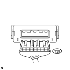
(a) Disconnect the T39 translate ECU connector.
|
|
|
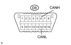
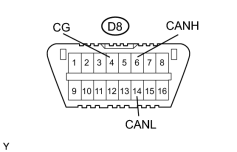
(b) Measure the resistance of the DLC3.
Standard resistance:
|
Tester Connection
|
Condition
|
Specified Condition
|
Proceed to
|
|
D8-6 (CANH) - D8-14 (CANL)
|
Ignition switch OFF
|
54 to 67 Ω
|
OK
|
|
D8-6 (CANH) - D8-14 (CANL)
|
Ignition switch OFF
|
67Ω or more
|
NG-A
|
|
D8-6 (CANH) - D8-14 (CANL)
|
Ignition switch OFF
|
54 Ω or less
|
NG-B
|
|
|
| NG-A |

|
CHECK CAN MAIN BUS LINE (FOR DISCONNECTION)
|
| NG-B |
|
CHECK CAN BUS WIRE (FOR SHORT CIRCUIT)
|
| OK |

|
|
(a) Reconnect the T39 translate ECU connector.
| NEXT |
|
|
|
|
3.
|
CHECK CAN BUS WIRE (FOR SHORT TO B+)
|
|
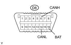
(a) Measure the resistance of the DLC3.
Standard resistance:
|
Tester Connection
|
Condition
|
Specified Condition
|
|
D8-6 (CANH) - D8-16 (BAT)
|
Ignition switch OFF
|
1 MΩ or higher
|
|
D8-14 (CANL) - D8-16 (BAT)
|
Ignition switch OFF
|
1 MΩ or higher
|
|
|
| NG |
|
CHECK CAN BUS WIRE (FOR SHORT TO B+)
|
| OK |
|
|
|
|
4.
|
CHECK CAN BUS WIRE (FOR SHORT TO GND)
|
|
(a) Measure the resistance of the DLC3.
Standard resistance:
|
Tester Connection
|
Condition
|
Specified Condition
|
|
D8-4 (CG) - D8-6 (CANH)
|
Ignition switch OFF
|
3 kΩ or higher
|
|
D8-4 (CG) - D8-14 (CANL)
|
Ignition switch OFF
|
3 kΩ or higher
|
|
|
| NG |
|
CHECK CAN BUS WIRE (FOR SHORT TO GND)
|
| OK |
|
HOW TO PROCEED WITH TROUBLESHOOTING
|
|

