| Last Modified: 4-30-2014 | 6.6 J | Doc ID: RM000000WRO006X |
| Model Year: 2006 | Model: LX470 | Prod Date Range: [05/2005 - ] |
| Title: 2UZ-FE ENGINE CONTROL SYSTEM: SFI SYSTEM: Cranking Holding Function Circuit; 2006 MY LX470 [05/2005 - ] | ||
|
Cranking Holding Function Circuit |
DESCRIPTION
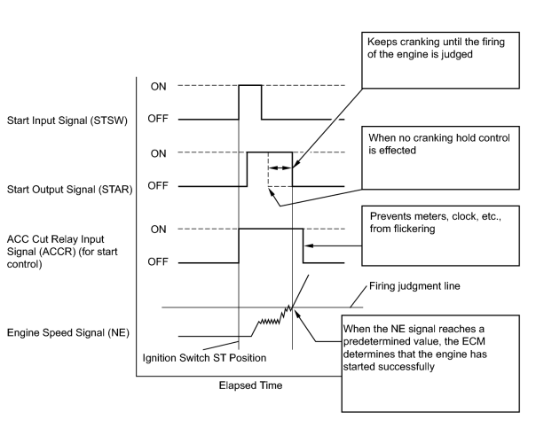
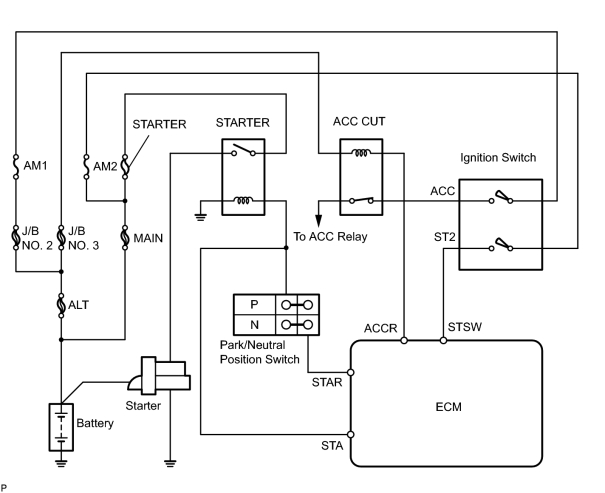
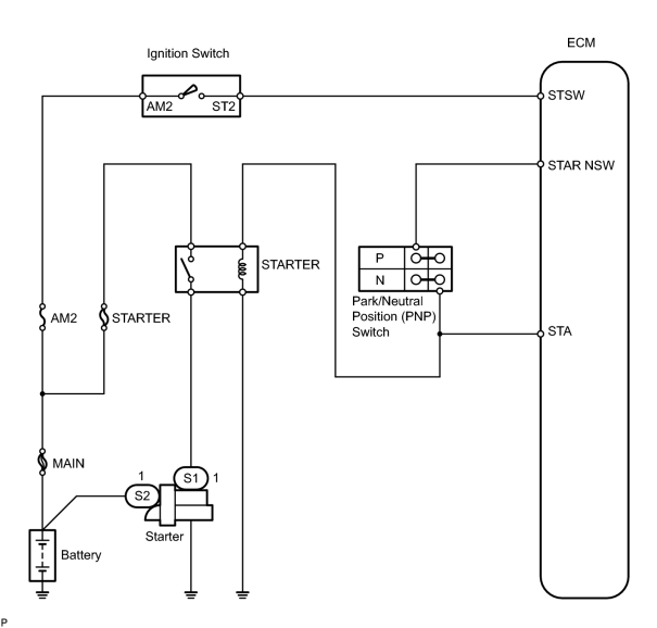
The starter is controlled by the ECM. When the ECM detects a start signal (STSW) from the ignition switch, this system monitors the engine speed (NE) and continues to operate the starter until it has determined that the engine has started (engine speed reaches approximately 500 rpm). If the engine is already running and the ignition switch is turned to START, the ECM will not operate the starter.
WIRING DIAGRAM
INSPECTION PROCEDURE
PROCEDURE
|
1. |
CHECK OPERATION OF ENGINE CRANKING |
(a) When turning the ignition switch to the START position check if the starter motor starts.
| OK |

|
|

|
2. |
READ VALUE USING INTELLIGENT TESTER (STA SIGNAL) |
(a) Connect the intelligent tester to the CAN VIM. Then connect the CAN VIM to the DLC3.
(b) Enter the following menu: DIAGNOSIS / ENHANCED OBDII / DATA LIST / PRIMARY / STARTER SIG.
(c) Confirm the starter signal status when the ignition switch is operated.
OK:
|
Ignition Switch Position |
STARTER SIG |
|---|---|
|
ON |
OFF |
|
Start |
ON |
| OK |
|
|
|
3. |
INSPECT ECM (STA AND STSW VOLTAGE) |
|
(a) Measure the voltage of the E6 ECM connector while cranking the engine (ignition switch is in the START position). Standard voltage:
|

|
| B |
|
| C |
|
|
|
4. |
INSPECT PARK / NEUTRAL POSITION SWITCH |
|
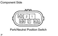
(a) Disconnect the P1 park / neutral position switch connector. (b) Measure the resistance between each terminal shown below when the shift lever is moved to each position. Standard resistance:
(c) Reconnect the park / neutral position switch connector. |
|
| NG |
|
| OK |
|
CHECK AND REPAIR HARNESS OR CONNECTOR (PARK / NEUTRAL POSITION SWITCH - ECM) |
|
5. |
INSPECT STARTER RELAY |
|
(a) Remove the starter relay from the engine room relay block. (b) Measure the resistance of the starter relay. Standard resistance:
(c) Reinstall the starter relay. |
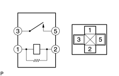
|
| NG |
|
|
|
6. |
CHECK HARNESS AND CONNECTOR (PARK / NEUTRAL POSITION SWITCH - STARTER RELAY, STARTER RELAY - BODY GROUND) |
(a)
Check harness and connector
![2006 MY LX470 [05/2005 - ]; INTRODUCTION: HOW TO TROUBLESHOOT ECU CONTROLLED SYSTEMS: ELECTRONIC CIRCUIT INSPECTION PROCEDURE](../../../../stylegraphics/info.gif "2006 MY LX470 [05/2005 - ]; INTRODUCTION: HOW TO TROUBLESHOOT ECU CONTROLLED SYSTEMS: ELECTRONIC CIRCUIT INSPECTION PROCEDURE") .
.
| NG |
|
|
|
7. |
INSPECT ENGINE ROOM RELAY BLOCK (STARTER RELAY VOLTAGE) |
|
(a) Remove the STARTER relay from the engine room relay block. (b) Measure the voltage of the engine room relay block and body ground. Standard voltage:
(c) Reinstall the STARTER relay. |
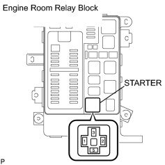
|
| NG |
|
CHECK AND REPAIR HARNESS AND CONNECTOR (STARTER RELAY - BATTERY) |
|
|
8. |
INSPECT STARTER ASSEMBLY |
(a)
Inspect starter assembly
.
| NG |
|
| OK |
|
CHECK AND REPAIR HARNESS OR CONNECTOR (STARTER RELAY - STARTER, STARTER - BATTERY) |
|
9. |
INSPECT IGNITION SWITCH ASSEMBLY |
|
(a) Disconnect the I18 ignition switch connector. (b) Measure the resistance of the connector terminals shown in the chart below. Standard resistance:
(c) Reconnect the I18 ignition switch connector. |
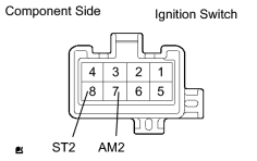
|
| NG |
|
| OK |
|
CHECK AND REPAIR HARNESS OR CONNECTOR (ECM - IGNITION SWITCH, IGNITION SWITCH - BATTERY) |

|

|