- Case 1:
| Last Modified: 4-30-2014 | 6.6 C | Doc ID: RM000000XOK00JX |
| Model Year: 2006 | Model: LX470 | Prod Date Range: [05/2005 - ] |
| Title: 2UZ-FE ENGINE CONTROL SYSTEM: SFI SYSTEM: P2238,P2239,P2241,P2242,P2252,P2253,P2255,P2256; Oxygen (A/F) Sensor Pumping Current Circuit Low (Bank 1 Sensor 1); 2006 MY LX470 [05/2005 - ] | ||
|
DTC |
P2238 |
Oxygen (A/F) Sensor Pumping Current Circuit Low (Bank 1 Sensor 1) |
|
DTC |
P2239 |
Oxygen (A/F) Sensor Pumping Current Circuit High (Bank 1 Sensor 1) |
|
DTC |
P2241 |
Oxygen (A/F) Sensor Pumping Current Circuit Low (Bank 2 Sensor 1) |
|
DTC |
P2242 |
Oxygen (A/F) Sensor Pumping Current Circuit High (Bank 2 Sensor 1) |
|
DTC |
P2252 |
Oxygen (A/F) Sensor Reference Ground Circuit Low (Bank 1 Sensor 1) |
|
DTC |
P2253 |
Oxygen (A/F) Sensor Reference Ground Circuit High (Bank 1 Sensor 1) |
|
DTC |
P2255 |
Oxygen (A/F) Sensor Reference Ground Circuit Low (Bank 2 Sensor 1) |
|
DTC |
P2256 |
Oxygen (A/F) Sensor Reference Ground Circuit High (Bank 2 Sensor 1) |
DESCRIPTION
HINT:
- Although the DTC titles refer to the "oxygen sensor", these DTCs relate to the Air Fuel Ratio (A/F) sensor.
- Sensor 1 refers to the sensor mounted in front of the Three-Way Catalytic Converter (TWC) and is located near the engine assembly.
Refer to DTC P2195
![2006 MY LX470 [05/2005 - ]; 2UZ-FE ENGINE CONTROL SYSTEM: SFI SYSTEM: P2195-P2198; Oxygen (A/F) Sensor Signal Stuck Lean (Bank 1 Sensor 1)](../../../../stylegraphics/info.gif "2006 MY LX470 [05/2005 - ]; 2UZ-FE ENGINE CONTROL SYSTEM: SFI SYSTEM: P2195-P2198; Oxygen (A/F) Sensor Signal Stuck Lean (Bank 1 Sensor 1)") .
.
|
DTC No. |
DTC Detection Condition |
Trouble Area |
|---|---|---|
|
P2238 P2241 |
Condition (a) or (b) continues for 5.0 seconds or more (1 trip detection logic): (a) AF+ voltage 0.5 V or less (b) (AF+) - (AF-) = 0.1 V or less
A/F sensor admittance: Less than 0.022 1/Ω (2 trip detection logic) |
|
|
P2239 P2242 |
AF+ voltage more than 4.5 V for 5.0 seconds or more (2 trip detection logic) |
|
|
P2252 P2255 |
AF- voltage 0.5 V or less for 5.0 seconds or more (2 trip detection logic) |
|
|
P2253 P2256 |
AF- voltage more than 4.5 V for 5.0 seconds or more (2 trip detection logic) |
|
HINT:
- DTCs P2238, P2239, P2252 and P2253 indicate malfunctions related to bank 1 A/F sensor circuit.
- DTCs P2241, P2242, P2255 and P2256 indicate malfunctions related to bank 2 A/F sensor circuit.
- Bank 1 refers to the bank that includes No. 1 cylinder.
- Bank 2 refers to the bank that includes No. 2 cylinder.
MONITOR DESCRIPTION
The Air Fuel Ratio (A/F) sensor varies its output voltage in proportion to the air fuel ratio. If the A/F sensor impedance (alternating current resistance) or output voltage deviates greatly from the standard range, the ECM determines that there is an open or short malfunction in the A/F sensor circuit.
MONITOR STRATEGY
|
Related DTCs |
P2238: A/F sensor (Bank 1) open circuit between AF+ and AF- P2238: A/F sensor (Bank 1) short circuit between AF+ and AF- P2238: A/F sensor (Bank 1) short circuit between AF+ and GND P2239: A/F sensor (Bank 1) short circuit between AF+ and +B P2241: A/F sensor (Bank 2) open circuit between AF+ and AF- P2241: A/F sensor (Bank 2) short circuit between AF+ and AF- P2241: A/F sensor (Bank 2) short circuit between AF+ and GND P2242: A/F sensor (Bank 2) short circuit between AF+ and +B P2252: A/F sensor (Bank 1) short circuit between AF- and GND P2253: A/F sensor (Bank 1) short circuit between AF- and +B P2255: A/F sensor (Bank 2) short circuit between AF- and GND P2256: A/F sensor (Bank 2) short circuit between AF- and +B |
|
Required Sensors/Components (Main) |
A/F sensor |
|
Required Sensors/Components (Related) |
Engine Coolant Temperature (ECT) sensor, Crankshaft position sensor |
|
Frequency of Operation |
Once per driving cycle |
|
Duration |
10 seconds: A/F sensor open circuit between AF+ and AF- 5 seconds: Others |
|
MIL Operation |
2 driving cycle |
|
Sequence of Operation |
None |
TYPICAL ENABLING CONDITIONS
|
Monitor runs whenever following DTCs not present |
None |
P2238 and P2241 (open circuit between AF+ and AF-):
|
Duration while all of following conditions met |
- |
|
AF+ terminal voltage |
0.5 to 4.5 V |
|
AF- terminal voltage |
0.5 to 4.5 V |
|
Difference between AF+ and AF- terminal voltages |
0.1 to 0.8 V |
|
ECT |
20°C (68°F) or more |
|
Engine condition |
Running |
|
Time after engine start |
50 seconds or more |
|
Fuel-cut |
OFF |
|
A/F sensor heater duty ratio |
0% or more |
|
Time after A/F sensor heating |
20 seconds or more |
|
Battery voltage |
10.5 V or more |
|
Ignition switch |
ON |
Others:
|
Battery voltage |
10.5 V or more |
|
Ignition switch |
ON |
TYPICAL MALFUNCTION THRESHOLDS
P2238 and P2241 (Open circuit between AF+ and AF-):
|
A/F sensor admittance |
Below 0.022 1/Ω |
P2238 and P2241 (Short circuit between AF+ and GND):
|
AF+ terminal voltage |
0.5 V or less |
P2238 and P2241 (Short circuit between AF+ and AF-):
|
Difference between AF+ and AF- terminal voltages |
0.1 V or less |
P2239 and P2242 (Short circuit between AF+ and +B):
|
AF+ terminal voltage |
More than 4.5 V |
P2252 and P2255 (Short circuit between AF- and GND):
|
AF- terminal voltage |
0.5 V or less |
P2253 and P2256 (Short circuit between AF- and +B):
|
AF- terminal voltage |
More than 4.5 V |
WIRING DIAGRAM
Refer to DTC P2195 (
).
INSPECTION PROCEDURE
HINT:
Intelligent tester only:
Malfunctioning areas can be identified by performing the A/F CONTROL function provided in the ACTIVE TEST. The A/F CONTROL function can help to determine whether the Air Fuel Ratio (A/F) sensor, Heated Oxygen (HO2) sensor and other potential trouble areas are malfunctioning.
The following instructions describe how to conduct the A/F CONTROL operation using the intelligent tester.
- Connect the intelligent tester to the CAN VIM. Then connect the CAN VIM to the DLC3.
- Start the engine and turn the tester ON.
- Warm up the engine at an engine speed of 2,500 rpm for approximately 90 seconds.
- On the tester, enter the following menus: DIAGNOSIS / ENHANCED OBD II / ACTIVE TEST / A/F CONTROL.
- Perform the A/F CONTROL operation with the engine in an idling condition (press the RIGHT or LEFT button to change the fuel injection volume).
- Monitor the output voltages of the A/F and HO2 sensors (AFS B1S1 and O2S B1S2 or AFS B2S1 and O2S B2S2) displayed on the tester.
HINT:
- The A/F CONTROL operation lowers the fuel injection volume by 12.5% or increases the injection volume by 25%.
- Each sensor reacts in accordance with increases and decreases in the fuel injection volume.
Standard:
|
Tester Display (Sensor) |
Injection Volume |
Status |
Voltage |
|---|---|---|---|
|
AFS B1S1 or AFS B2S1 (A/F) |
+25% |
Rich |
Less than 3.0 |
|
AFS B1S1 or AFS B2S1 (A/F) |
-12.5% |
Lean |
More than 3.35 |
|
O2S B1S2 or O2S B2S2 (HO2) |
+25% |
Rich |
More than 0.55 |
|
O2S B1S2 or O2S B2S2 (HO2) |
-12.5% |
Lean |
Less than 0.4 |
NOTICE:
The Air Fuel Ratio (A/F) sensor has an output delay of a few seconds and the Heated Oxygen (HO2) sensor has a maximum output delay of approximately 20 seconds.
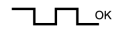
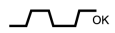
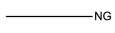
|
Case |
A/F Sensor (Sensor 1) Output Voltage |
HO2 Sensor (Sensor 2) Output Voltage |
Main Suspected Trouble Areas |
||
|---|---|---|---|---|---|
|
1 |
Injection Volume +25% -12.5% |

|
Injection Volume +25% -12.5% |
|
- |
|
Output Voltage More than 3.35 V Less than 3.0 V |
|
Output Voltage More than 0.55 V Less than 0.4 V |
|
||
|
2 |
Injection Volume +25% -12.5% |
|
Injection Volume +25% -12.5% |
|
|
|
Output Voltage Almost no reaction |
|
Output Voltage More than 0.55 V Less than 0.4 V |
|
||
|
3 |
Injection Volume +25% -12.5% |
|
Injection Volume +25% -12.5% |
|
|
|
Output Voltage More than 3.35 V Less than 3.0 V |
|
Output Voltage Almost no reaction |
|
||
|
4 |
Injection volume +25% -12.5% |
|
Injection Volume +25% -12.5% |
|
|
|
Output Voltage Almost no reaction |
|
Output Voltage Almost no reaction |
|
||
- Following the A/F CONTROL procedure enables technicians to check and graph the output voltages of both the A/F and HO2 sensors.
- To display the graph, enter the following menus: DIAGNOSIS / ENHANCED OBD II / ACTIVE TEST / A/F CONTROL / USER DATA / AFS B1S1 and O2S B1S2 or AFS B2S1 and O2S B2S2. Then press the YES button and ENTER button, followed by the F4 button.
HINT:
Read freeze frame data using the intelligent tester. Freeze frame data records the engine conditions when malfunctions are detected. When troubleshooting, freeze frame data can help determine if the vehicle was moving or stationary, if the engine was warmed up or not, if the air fuel ratio was lean or rich, and other data from the time the malfunction occurred.
PROCEDURE
|
1. |
INSPECT AIR FUEL RATIO SENSOR (HEATER RESISTANCE) |
|
(a) Disconnect the A53 or A54 Air Fuel Ratio (A/F) sensor connector. (b) Measure the resistance of the A/F sensor connector. Standard resistance:
(c) Reconnect the A/F sensor connector. |

|
| NG |

|
|

|
2. |
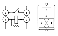
INSPECT A/F RELAY (Marking: A/F HTR) |
|
(a) Remove the A/F relay from the No. 8 engine room relay block. (b) Measure the resistance of the A/F relay. Standard resistance:
(c) Reinstall the A/F relay. |
|
| NG |
|
|
|
3. |
CHECK HARNESS AND CONNECTOR (A/F SENSOR - ECM) |
(a)
Check harness and connector
.
| NG |
|
| OK |
|

|

|