| Last Modified: 4-30-2014 | 6.6 J | Doc ID: RM000000XP200EX |
| Model Year: 2006 | Model: LX470 | Prod Date Range: [05/2005 - ] |
| Title: A750F AUTOMATIC TRANSMISSION: AUTOMATIC TRANSMISSION SYSTEM: Pattern Select Switch Power Mode Circuit; 2006 MY LX470 [05/2005 - ] | ||
|
Pattern Select Switch Power Mode Circuit |
DESCRIPTION
The ECM memory contains the shift programs for the NORMAL and POWER patterns, 2 position, L position and lock-up patterns. Following the programs corresponding to the signals from the pattern select switch, the park/neutral position and other various sensors, the ECM switches the solenoid valves ON and OFF, and controls the transmission gear change and the lock-up clutch operation.
WIRING DIAGRAM
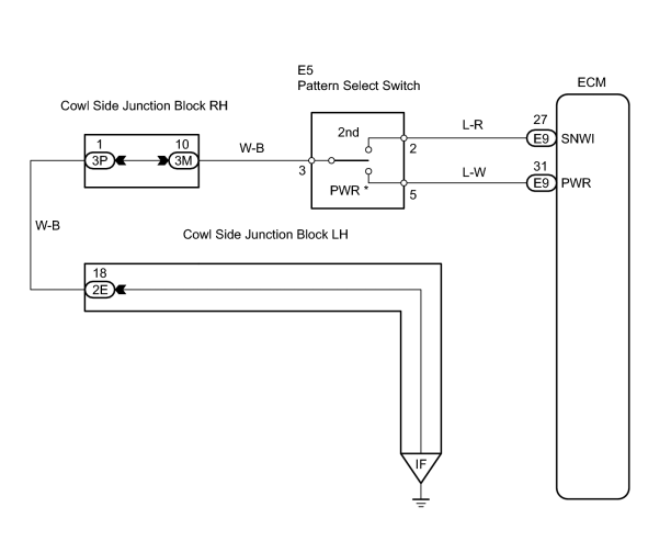
HINT:
*: Pattern select switch (PWR mode switch)
When the PWR mode switch is pushed, the switch contact is made and the PWR mode is selected.
To cancel the PWR mode, push the PWR mode switch once again.
INSPECTION PROCEDURE
PROCEDURE
|
1. |
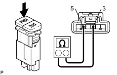
INSPECT PATTERN SELECT SWITCH (PWR mode switch) |
(a) Disconnect the E5 pattern select switch connector.
|
(b) Measure the resistance of the switch. Standard resistance:
|
|
| NG |

|
|

|
2. |
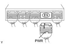
CHECK WIRE HARNESS (PATTERN SELECT SWITCH - BODY GROUND) |
|
(a) Disconnect the E5 pattern select switch connector. (b) Measure the resistance of the wire harness side connector. Standard resistance:
|
|
| NG |
|
| OK |
|
PROCEED TO NEXT CIRCUIT INSPECTION SHOWN IN PROBLEM SYMPTOMS TABLE |

|

|