- Open or short in Mass Air Flow (MAF) meter circuit
- Mass Air Flow (MAF) meter
- ECM
| Last Modified: 4-30-2014 | 6.6 C | Doc ID: RM000000YDP00BX |
| Model Year: 2006 | Model: LX470 | Prod Date Range: [05/2005 - ] |
| Title: 2UZ-FE ENGINE CONTROL SYSTEM: SFI SYSTEM: P0100,P0102,P0103; Mass Air Flow Circuit Malfunction; 2006 MY LX470 [05/2005 - ] | ||
|
DTC |
P0100 |
Mass Air Flow Circuit Malfunction |
|
DTC |
P0102 |
Mass Air Flow Circuit Low |
|
DTC |
P0103 |
Mass Air Flow Circuit High |
DESCRIPTION
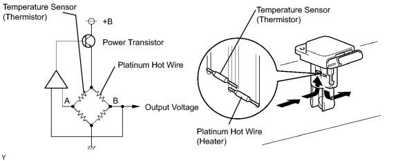
The Mass Air Flow (MAF) meter measures the amount of air flowing through the throttle valve. The ECM uses this information to determine the fuel injection time and provide a proper air fuel ratio. Inside the MAF meter, there is a heated platinum wire exposed to the flow of intake air.
By applying a specific current to the wire, the ECM heats this wire to a given temperature. The flow of incoming air cools the wire and an internal thermistor, affecting their resistance. To maintain a constant current value, the ECM varies the voltage applied to these components in the MAF meter. The voltage level is proportional to the air flow through the sensor. The ECM interprets this voltage as the intake air amount.
The circuit is constructed so that the platinum hot wire and temperature sensor provide a bridge circuit, with the power transistor controlled so that the potential of A and B remains equal to maintain the set temperature.
|
DTC No. |
DTC Detection Condition |
Trouble Area |
|---|---|---|
|
P0100 |
Open or short in Mass Air Flow (MAF) meter circuit with more than 3 seconds at engine speed 4,000 rpm or less (1 trip detection logic) |
|
|
P0102 |
Open or short in MAF meter circuit with more than 3 seconds at engine speed 4,000 rpm or less (1 trip detection logic) |
|
|
P0103 |
Open to EVG in MAF meter circuit with more than 3 seconds at engine speed 4,000 rpm or less Short to +B in MAF meter circuit with more than 3 seconds at engine speed 4,000 rpm or less (1 trip detection logic) |
|
HINT:
After confirming DTC P0100, P0102 or P0103, use the intelligent tester to confirm the MAF (to reach the MAF menu: DIAGNOSIS / ENHANCED OBD II / DATA LIST / PRIMARY).
|
Mass Air Flow Rate (gm/s) |
Malfunction |
|---|---|
|
Approximately 0.0 |
|
|
271.0 or more |
E2G circuit open |
MONITOR DESCRIPTION
If there is a defect in the Mass Air Flow (MAF) meter or an open or short circuit, the voltage level will deviate outside the normal operating range. The ECM interprets this deviation as a defect in the MAF meter and sets a DTC.
Example:
When the sensor output voltage is less than 0.2 V or more than 4.9 V and if either condition continues for more than 3 seconds, the ECM will set a DTC.
This monitor runs for 3 seconds (the first 3 seconds of engine idle) after the engine is started (1 trip detection logic).
MONITOR STRATEGY
|
Related DTCs |
P0100: MAF meter range check (fluttering) P0102: MAF meter range check (low voltage) P0103: MAF meter range check (high voltage) |
|
Required Sensors/Components (Main) |
MAF meter |
|
Required Sensors/Components (Related) |
Crankshaft position sensor |
|
Frequency of operation |
Continuous |
|
Duration |
3 seconds |
|
MIL operation |
Immediate: Engine RPM is less than 4,000 rpm 2 driving cycles: Engine RPM is 4,000 rpm or more |
|
Sequence of operation |
None |
TYPICAL ENABLING CONDITIONS
|
Monitor runs whenever following DTCs not present |
None |
TYPICAL MALFUNCTION THRESHOLDS
P0100:
|
MAF meter voltage |
Less than 0.2 V or more than 4.9 V |
P0102:
|
MAF meter voltage |
Less than 0.2 V |
P0103:
|
MAF meter voltage |
More than 4.9 V |
COMPONENT OPERATING RANGE
|
MAF meter voltage |
Between 0.4 and 2.2 V |
WIRING DIAGRAM
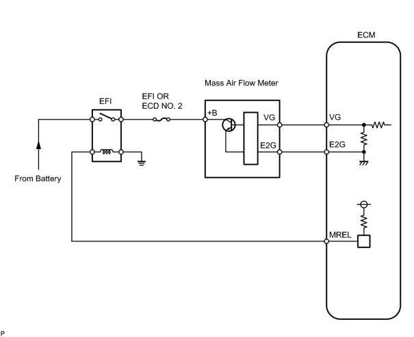
INSPECTION PROCEDURE
HINT:
Read freeze frame data using the intelligent tester. Freeze frame data records the engine conditions when malfunctions are detected. When troubleshooting, freeze frame data can help determine if the vehicle was running or stopped, if the engine was warmed up or not, if the air fuel ratio was lean or rich, and other data from the time the malfunction occurred.
PROCEDURE
|
1. |
READ VALUE USING INTELLIGENT TESTER (MASS AIR FLOW RATE) |
(a) Connect the intelligent tester to the CAN VIM. Then connect the CAN VIM to the DLC3.
(b) Allow the engine to idle.
(c) Enter the following menus: DIAGNOSIS / ENHANCED OBD II / DATA LIST / PRIMARY / MAF.
(d) Read the values displayed on the tester.
|
Mass Air Flow Rate (g/second) |
Proceed to |
|---|---|
|
0.0 |
A |
|
271.0 or more |
B |
|
MAF rate greater than 1 but less than 270.0* |
C |
HINT:
*: The value must change when the throttle valve is opened or closed.
| B |

|
| C |
|
|

|
2. |
INSPECT MASS AIR FOW METER (POWER SOURCE VOLTAGE) |
|
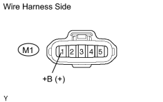
(a) Turn the ignition switch ON. (b) Disconnect the M1 Mass Air Flow (MAF) meter connector. (c) Measure the voltage of the wire harness side connector. Standard voltage:
|
|
| NG |
|
|
|
3. |
INSPECT ECM (VG VOLTAGE) |
|
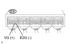
(a) Start the engine. (b) Measure the voltage of the E8 ECM connector. HINT: Move the shift lever to P or N and turn the A/C switch OFF. Standard voltage:
|
|
| OK |
|
|
|
4. |
CHECK HARNESS AND CONNECTOR (MASS AIR FLOW METER - ECM) |
(a)
Check harness and connector
![2006 MY LX470 [05/2005 - ]; INTRODUCTION: HOW TO TROUBLESHOOT ECU CONTROLLED SYSTEMS: ELECTRONIC CIRCUIT INSPECTION PROCEDURE](../../../../stylegraphics/info.gif "2006 MY LX470 [05/2005 - ]; INTRODUCTION: HOW TO TROUBLESHOOT ECU CONTROLLED SYSTEMS: ELECTRONIC CIRCUIT INSPECTION PROCEDURE") .
.
| NG |
|
| OK |
|
|
5. |
CHECK HARNESS AND CONNECTOR (MASS AIR FLOW METER - INTEGRATION RELAY) |
(a)
Check harness and connector
.
| NG |
|
| OK |
|
|
6. |
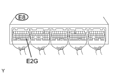
INSPECT ECM (SENSOR GROUND) |
|
(a) Measure the resistance of the ECM connector. Standard resistance:
|
|
| NG |
|
|
|
7. |
CHECK HARNESS AND CONNECTOR (MASS AIR FLOW METER - ECM) |
(a)
Check harness and connector
.
| NG |
|
| OK |
|

|

|