-
Conditions (a), (b) and (c) are met:
- (a) Cold start
- (b) After sufficient warm-up time has elapsed
- (c) ECT is less than 75°C (167°F)
| Last Modified: 4-30-2014 | 6.6 C | Doc ID: RM000000YDV007X |
| Model Year: 2006 | Model: LX470 | Prod Date Range: [05/2005 - ] |
| Title: 2UZ-FE ENGINE CONTROL SYSTEM: SFI SYSTEM: P0128; Thermostat Malfunction; 2006 MY LX470 [05/2005 - ] | ||
|
DTC |
P0128 |
Thermostat Malfunction |
DESCRIPTION
This DTC is output when the Engine Coolant Temperature (ECT) does not reach 75°C (167°F) despite sufficient engine warm-up time.
|
DTC No. |
DTC Detection Condition |
Trouble Area |
|---|---|---|
|
P0128 |
|
|
MONITOR DESCRIPTION
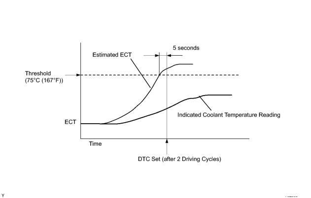
The ECM estimates the coolant temperature based on starting temperature, engine loads, and engine speeds. The ECM then compares the estimated temperature with the actual ECT. When the estimated coolant temperature reaches 75°C (167°F), the ECM checks the actual ECT. If the actual ECT is less than 75°C (167°F), the ECM will interpret this as a fault in the engine cooling system or thermostat and set a DTC.
MONITOR STRATEGY
|
Related DTCs |
P0128: Coolant thermostat |
|
Required Sensors/Components (Main) |
Thermostat |
|
Required Sensors/Components (Related) |
Engine coolant temperature sensor, Intake air temperature sensor, Vehicle speed sensor |
|
Frequency of Operation |
Once per drive cycle |
|
Duration |
15 minutes |
|
MIL Operation |
2 driving cycles |
|
Sequence of Operation |
None |
TYPICAL ENABLING CONDITIONS
|
Monitor will run whenever these DTCs are not present |
P0010, P0020 (OCV Bank 1, 2) P0011 (VVT System 1 - Advance) P0012 (VVT System 1 - Retard) P0021 (VVT System 2 - Advance) P0022 (VVT System 2 - Retard) P0031, P0032, P0051, P0052 (A/F sensor heater - Sensor 1) P0100 - P0103 (MAF meter) P0110 - P0113 (IAT sensor) P0115 - P0118 (ECT sensor) P0125 (Insufficient ECT for closed loop) P0171, P0172 (Fuel system) P0300 - P0308 (Misfire) P0335 (CKP sensor) P0340, P0341 (CMP sensor) P0351 - P0358 (igniter) P0500 (VSS) P2196, P2198 (A/F sensor - rationality) P2A00, P2A03 (A/F sensor - slow response) |
|
Battery voltage |
11 V or higher |
|
One of the following conditions 1 or 2 is met |
- |
|
1. All of the following conditions (a), (b) and (c) are met |
- |
|
(a) ECT at engine start - IAT at engine start |
-15 to 7°C (5 to 12.6°F) |
|
(b) ECT at engine start |
-10 to 56°C (14 to 132.8°F) |
|
(c) IAT at engine start |
-10 to 56°C (14 to 132.8°F) |
|
2. All of the following conditions (a), (b) and (c) are met |
- |
|
(a) ECT at engine start - IAT at engine start |
Higher than 7°C (12.6°F) |
|
(b) ECT at engine start |
56°C (133°F) or lower |
|
(c) IAT at engine start |
-10°C (14°F) or higher |
|
Accumulated time that vehicle speed is 128 km/h (80 mph) or more |
Less than 20 seconds |
TYPICAL MALFUNCTION THRESHOLDS
|
Duration that all of following conditions are met |
5 seconds or more |
|
(a) Estimated ECT |
75°C (167°F) or higher |
|
(b) ECT sensor voltage |
Lower than 75°C (167°F) |
MONITOR RESULT
Detailed information on Checking Monitor Status
![2006 MY LX470 [05/2005 - ]; 2UZ-FE ENGINE CONTROL SYSTEM: SFI SYSTEM: CHECKING MONITOR STATUS](../../../../stylegraphics/info.gif "2006 MY LX470 [05/2005 - ]; 2UZ-FE ENGINE CONTROL SYSTEM: SFI SYSTEM: CHECKING MONITOR STATUS") .
.
The test value and test limit information are in the following table. Check the monitor result and test values after performing the monitor drive pattern (refer to "Confirmation Monitor").
- Monitor Identification Data (MID) is assigned to each emissions-related component.
- Test Identification Data (TID) is assigned to each test value.
- Scaling is used to calculate the test value indicated on generic OBD II scan tools.
Thermostat
|
MID |
TID |
Scaling |
Description of Test Value |
Minimum Test Limit |
Maximum Test Limit |
|---|---|---|---|---|---|
|
$E1 |
$E8 |
Multiply by 01 [°C] |
ECT sensor output when estimated ECT reaches to malfunction criteria |
Malfunction criteria |
Maximum test limit |
INSPECTION PROCEDURE
HINT:
Read freeze frame data using the intelligent tester. Freeze frame data records the engine conditions when malfunctions are detected. When troubleshooting, freeze frame data can help determine if the vehicle was running or stopped, if the engine was warmed up or not, if the air fuel ratio was lean or rich, and other data from the time the malfunction occurred.
PROCEDURE
|
1. |
CHECK OTHER DTC OUTPUT (IN ADDITION TO DTC P0128) |
(a) Connect the intelligent tester to the CAN VIM. Then connect the CAN VIM to the DLC3.
(b) Turn the ignition switch ON and turn the intelligent tester ON.
(c) Enter the following menus: DIAGNOSIS / ENHANCED II / DTC INFO / CURRENT CODES.
(d) Read the DTC.
Result:
|
Display (DTC output) |
Proceed to |
|---|---|
|
P0128 |
A |
|
P0128 and other DTCs |
B |
HINT:
If any other codes besides P0128 are output, perform the troubleshooting for those DTCs first.
| B |

|
|

|
2. |
CHECK COOLING SYSTEM |
(a) Check for defects in the cooling system that might cause the system to be too cold, such as an abnormal radiator fan operation or a modified cooling system.
(b) Check the valve opening temperature of the thermostat.
OK:
Valve opening temperature is 80 to 84°C (176 to 183°F)
HINT:
Also check that the valve is completely closed below the opening temperature shown above.
| NG |
|
|
|
3. |
INSPECT THERMOSTAT |
(a)
Remove the thermostat
.
(b) Check the valve opening temperature of the thermostat.
Standard:
80 to 84°C (176 to 183°F)
HINT:
In addition to the above check, confirm that the valve is completely closed when the temperature is below the standard.
(c)
Reinstall the thermostat
.
| NG |
|
| OK |
|

|

|