- No VVT sensor signal to ECM during cranking (2 trip detection logic)
- No VVT sensor signal to ECM with engine speed 600 rpm or more (1 trip detection logic)
| Last Modified: 4-30-2014 | 6.6 C | Doc ID: RM000000YE1007X |
| Model Year: 2006 | Model: LX470 | Prod Date Range: [05/2005 - ] |
| Title: 2UZ-FE ENGINE CONTROL SYSTEM: SFI SYSTEM: P0340,P0341,P0345,P0346; Camshaft Position Sensor Circuit Malfunction; 2006 MY LX470 [05/2005 - ] | ||
|
DTC |
P0340 |
Camshaft Position Sensor Circuit Malfunction |
|
DTC |
P0341 |
Camshaft Position Sensor "A" Circuit Range / Performance (Bank 1 or Single Sensor) |
|
DTC |
P0345 |
Camshaft Position Sensor "A" Circuit (Bank 2) |
|
DTC |
P0346 |
Camshaft Position Sensor "A" Circuit Range / Performance (Bank 2) |
DESCRIPTION
The Variable Valve Timing (VVT) sensor consists of a magnet, iron core and pickup coil. The camshaft timing rotor has 3 teeth on its outer circumference and is installed on the intake camshaft. When the camshafts rotate, change occur on the camshaft protrusions and the pickup coil air gaps. These changes cause fluctuations in the magnetic field and generate voltage in the pickup coil.
Each sensor monitors its camshaft timing rotor, which is located on the camshaft. The ECM uses the sensor to detect the camshaft angle. The camshaft rotation synchronizes with the crankshaft rotation, and this sensor communicates the rotation of the camshaft timing rotor as a pulse signal to the ECM. Based on the signal, the ECM controls camshaft position.
|
DTC No. |
DTC Detection Condition |
Trouble Area |
|---|---|---|
|
P0340 P0345 |
|
|
|
P0341 P0346 |
While crankshaft rotates twice, VVT sensor signal is input to ECM 12 times or more (1 trip detection logic) |
Same as DTC No. P0340/P0345 |
HINT:
-
DTC P0340 and P0345 indicate a malfunction related to the VVT sensor (+) circuit
(wire harness (from ECM to VVT sensor) and VVT sensor).
-
DTC P0341 and P0346 indicate a malfunction related to the VVT sensor (-) circuit
(wire harness (from ECM to VVT sensor) and VVT sensor).
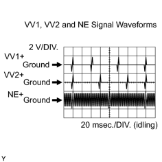
-
Reference: Inspect using an oscilloscope.
During cranking or idling, check the waveform of the ECM connector.
|
Tester Connection |
Specified Condition |
|---|---|
|
E6-25 (VV1+) - E6-24 (VV1-) |
Correct waveform is as shown |
|
E6-18 (VV2+) - E6-28 (VV2-) |
Correct waveform is as shown |
|
E6-21 (NE+) - E6-20 (NE-) |
Correct waveform is as shown |
MONITOR DESCRIPTION
If there is no signal from the VVT sensor even though the engine is revolving, or if the rotation of the camshaft and the crankshaft is not synchronized, the ECM interprets this as a malfunction of the sensor.
This monitor runs for 10 seconds (the first 10 seconds of engine idle) after the engine is started.
MONITOR STRATEGY
|
Related DTCs |
P0340: VVT sensor (bank 1) range check / rationality P0341: VVT sensor (bank 1) range check / rationality P0345: VVT sensor (bank 2) range check / rationality P0346: VVT sensor (bank 2) range check / rationality |
|
Required Sensors/Components (Main) |
VVT sensor |
|
Required Sensors/Components (Related) |
Crankshaft position sensor |
|
Frequency of Operation |
Continuous |
|
Duration |
5 seconds |
|
MIL Operation |
P0340, P0345 case 1: 2 driving cycles P0340, P0345 case 2, P0341, P0346: Immediate |
|
Sequence of Operation |
None |
TYPICAL ENABLING CONDITIONS
All:
|
Monitor will run whenever these DTCs are not present |
None |
P0340, P0345 Case 1:
|
Starter |
ON |
|
Minimal battery voltage while starter ON |
Less than 11 V |
P0340, P0345 Case 2:
|
Engine RPM |
600 rpm or more |
|
Starter |
OFF |
|
Battery voltage |
8 V or more |
|
Ignition switch |
ON |
P0341, P0346:
|
Starter |
After OFF to ON timing |
|
Engine revolution |
720°CA |
TYPICAL MALFUNCTION THRESHOLDS
P0340, P0345 Case 1:
|
VVT sensor signal |
No signal |
P0340, P0345 Case 2:
|
VVT sensor signal |
No signal |
P0341, P0346:
|
VVT sensor count |
12 or more / 720°CA (=Engine 2 revolutions) |
COMPONENT OPERATING RANGE
|
VVT sensor signal input during every 720°CA |
3 |
WIRING DIAGRAM
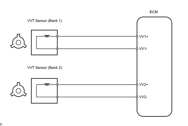
INSPECTION PROCEDURE
HINT:
- If DTC P0340 and P0341 are displayed, check the left bank VVT sensor.
- If DTC P0345 and P0346 are displayed, check the right bank VVT sensor.
- Read freeze frame data using the intelligent tester. Freeze frame data records the engine conditions when malfunctions are detected. When troubleshooting, freeze frame data can help determine if the vehicle was running or stopped, if the engine was warmed up or not, if the air fuel ratio was lean or rich, and other data from the time the malfunction occurred.
PROCEDURE
|
1. |
INSPECT VVT SENSOR (RESISTANCE) |
|
(a) Disconnect the C42 and C43 VVT sensor connectors. (b) Measure the resistance of the VVT sensor. Standard resistance:
NOTICE: In the above chart, the terms "cold" and "hot" refer to the temperature of the coils. "Cold" means approximately -10 to 50°C (14 to 122°F). "Hot" means approximately 50 to 100°C (122 to 212°F). |
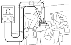
|
| NG |

|
|

|
2. |
CHECK HARNESS AND CONNECTOR (VVT SENSOR - ECM) |
(a)
Check harness and connector
![2006 MY LX470 [05/2005 - ]; INTRODUCTION: HOW TO TROUBLESHOOT ECU CONTROLLED SYSTEMS: ELECTRONIC CIRCUIT INSPECTION PROCEDURE](../../../../stylegraphics/info.gif "2006 MY LX470 [05/2005 - ]; INTRODUCTION: HOW TO TROUBLESHOOT ECU CONTROLLED SYSTEMS: ELECTRONIC CIRCUIT INSPECTION PROCEDURE") .
.
| NG |
|
|
|
3. |
CHECK SENSOR INSTALLATION (VVT SENSOR) |
|
(a) Check the sensor installation. OK: Sensor is installed correctly. |
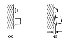
|
| NG |
|
|
|
4. |
CHECK CAMSHAFT (TOOTH) |
(a)
Remove the cylinder head cover
.
(b) Check the tooth of the camshaft.
| NG |
|
| OK |
|

|

|