- EVAP pressure just after reference pressure measurement greater than -1 kPa-g (755 mmHg-a)
- Reference pressure less than -4.85 kPa-g (726 mmHg-a)
- Reference pressure greater than -1 kPa-g (755 mmHg-a)
- Reference pressure is not saturated
- Reference pressure difference between first and second is 0.7 kPa-g (5 mmHg-g) or more
| Last Modified: 4-30-2014 | 6.6 C | Doc ID: RM000000YE9007X |
| Model Year: 2006 | Model: LX470 | Prod Date Range: [05/2005 - 01/2006] |
| Title: 2UZ-FE ENGINE CONTROL SYSTEM: SFI SYSTEM: P2401,P2402; Evaporative Emission Leak Detection Pump Stuck OFF; 2006 MY LX470 [05/2005 - 01/2006] | ||
|
DTC |
P2401 |
Evaporative Emission Leak Detection Pump Stuck OFF |
|
DTC |
P2402 |
Evaporative Emission Leak Detection Pump Stuck ON |
DTC SUMMARY
|
DTC No. |
Monitoring Item |
Malfunction Detection Condition |
Trouble Area |
Detection Timing |
Detection Logic |
|---|---|---|---|---|---|
|
P2401 |
Leak detection pump stuck OFF |
P043E, P043F, P2401, P2402 and P2419 are present when one of the following conditions is met during key-off EVAP monitor: HINT: These values are typical |
|
Ignition switch OFF |
2 trip |
|
P2402 |
Leak detection pump stuck ON |
P043E, P043F, P2401, P2402 and P2419 are present when one of the following conditions is met during key-off EVAP monitor:
HINT: These values are typical |
|
Ignition switch OFF |
2 trip |
DESCRIPTION
The circuit description can be found in the Evaporative Emission (EVAP) system
![2006 MY LX470 [05/2005 - 01/2006]; 2UZ-FE ENGINE CONTROL SYSTEM: SFI SYSTEM: EVAP System](../../../../stylegraphics/info.gif "2006 MY LX470 [05/2005 - 01/2006]; 2UZ-FE ENGINE CONTROL SYSTEM: SFI SYSTEM: EVAP System") .
.
INSPECTION PROCEDURE
Refer to the EVAP system
.
MONITOR DESCRIPTION
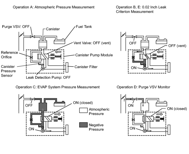
5 hours* after the ignition switch is turned OFF, the leak detection pump creates negative pressure (vacuum) in the EVAP system. The ECM monitors for leaks and actuator malfunctions based on the EVAP pressure.
HINT:
*: If the engine coolant temperature is not below 35°C (95°F) 5 hours after the ignition switch is turned OFF, the monitor check starts 2 hours later. If it is still not below 35°C (95°F) 7 hours after the ignition switch is turned OFF, the monitor check starts 2.5 hours later.
|
Sequence |
Operation |
Description |
Duration |
|---|---|---|---|
|
- |
ECM activation |
Activated by soak timer 5, 7 or 9.5 hours after ignition switch OFF. |
- |
|
A |
Atmospheric pressure measurement |
Vent valve turned OFF (vent) and EVAP system pressure measured by ECM in order to register atmospheric pressure. If pressure in EVAP system not between 70 kPa and 110 kPa (525 mmHg and 825 mmHg), ECM cancels EVAP system monitor. |
10 seconds |
|
B |
First 0.02 inch leak criterion measurement |
In order to determine 0.02 inch leak criterion, leak detection pump creates negative pressure (vacuum) through reference orifice and then ECM checks if leak detection pump and vent valve operate normally. |
60 seconds |
|
C |
EVAP system pressure measurement |
Vent valve turned ON (closed) to shut EVAP system. Negative pressure (vacuum) created in EVAP system, and EVAP system pressure then measured. Write down measured value as it will be used in leak check. If EVAP pressure does not stabilize within 900 seconds, ECM cancels EVAP system monitor. |
900 seconds* |
|
D |
Purge VSV monitor |
Purge VSV opened and then EVAP system pressure measured by ECM. Large increase indicates normal. |
10 seconds |
|
E |
Second 0.02 inch leak criterion measurement |
After second 0.02 inch leak criterion measurement, leak check performed by comparing first and second 0.02 inch leak criterion. If stabilized system pressure higher than second 0.02 inch leak criterion, ECM determines that EVAP system leaking. |
60 seconds |
|
F |
Final check |
Atmospheric pressure measured and then monitoring result recorded by ECM. |
- |
*: If only a small amount of fuel is in the fuel tank, it takes longer for the EVAP pressure to stabilize.
-
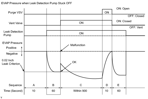
P2401: Leak detection pump stuck OFF
In operation B, the leak detection pump creates negative pressure (vacuum) through the reference orifice. The EVAP system pressure is then measured by the ECM using the canister pressure sensor to determine the 0.02 inch leak criterion. If the pressure is higher than -1.06 kPa (-7.95 mmHg)* or lower than -4.85kPa (-36.38 mmHg)*, the ECM interprets this as the leak detection pump being stuck OFF (not operating). The ECM then illuminates the MIL and sets the DTC (2 trip detection logic).
*: The threshold varies according to the atmospheric pressure measured in operation A. The values described above are based on an atmospheric pressure of 100 kPa (750.1 mmHg): absolute pressure.
-
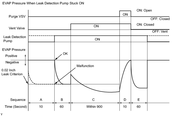
P2402: Leak detection pump stuck ON
In operation B, the leak detection pump creates negative pressure (vacuum) through the reference orifice. The EVAP system pressure is then measured by the ECM using the canister pressure sensor to determine the 0.02 inch leak criterion. If the pressure is higher than -1.06 kPa (-7.95 mmHg)* or lower than -4.85 Ka (-36.38 mmHg)*, the ECM interprets this as the leak detection pump being stuck ON (operating all the time). The ECM illuminates the MIL and sets the DTC (2 trip detection logic).
*: The threshold varies according to the atmospheric pressure measured in operation A. The values described above are based on an atmospheric pressure of 100 kPa (750.1 mmHg): absolute pressure.
HINT:
The detection logic of DTCs P2401 and P2402 is the same because in both cases the 0.02 inch leak criterion measured in operation B is compared to the atmospheric pressure registered in operation A. The ECM calculates the difference between these pressures by deducting [the 0.02 inch leak criterion] from [the stored atmospheric pressure], and uses this to monitor the EVAP system pressure change.
MONITOR STRATEGY
|
Required Sensors/Components |
Purge VSV and canister pump module |
|
Frequency of Operation |
Once per driving cycle |
|
Duration |
Within 2 minutes |
|
MIL Operation |
2 driving cycles |
|
Sequence of Operation |
None |
TYPICAL ENABLING CONDITIONS
|
Enable conditions of EVAP key-OFF monitor |
|
|
P043E (Reference orifice - low flow) P043F (Reference orifice - high flow) P0441 (Purge VSV - stuck open) P0441 (Purge VSV - stuck close) P0451 (Canister pressure sensor - noise) P0455 (EVAP gross leak) P0456 (EVAP 0.02 inch leak) P2401 (Leak detection pump - stuck OFF) P2402 (Leak detection pump - stuck ON) P2419 (Vent valve - stuck ON) P2420 (Vent valve - stuck OFF) |
|
|
Atmospheric pressure |
70 to 110 kPa (525 to 825 mmHg) |
|
Battery voltage |
10.5 V or higher |
|
Vehicle speed |
4 km/h (2.5 mph) or less |
|
Ignition switch |
OFF |
|
Time after key off |
5 or 7 or 9.5 hours |
|
Canister pressure sensor malfunction (P0450, P0452, P0453) |
Not detected |
|
Purge VSV |
Not operated by scan tool |
|
Vent valve |
Not operated by scan tool |
|
Leak detection pump |
Not operated by scan tool |
|
Both of the following conditions 1 and 2 are met before key off |
- |
|
1. Duration that vehicle has been driven |
5 minutes or more |
|
2. EVAP purge operation |
Performed |
|
ECT |
4.4 to 35°C (40 to 95°F) |
|
IAT |
4.4 to 35°C (40 to 95°F) |
|
Example of re-start time |
- |
|
First time |
7 house |
|
Second time |
9 hours and 30 minutes |
1. Key-off monitor sequence 1 to 8
1. Atmospheric pressure measurement
|
Next sequence is run if the following condition is met |
- |
|
Atmospheric pressure change |
Within 0.3 kPa (2.25 mmHg) in 1 second |
2. First reference pressure measurement
|
Next sequence is run if the following conditions are met |
- |
|
EVAP pressure just after reference pressure measurement start |
-1 kPa (-7.5 mmHg) or lower |
|
Reference pressure |
-4.85 to -1.05 kPa (726 to 754 mmHg) |
|
Reference pressure |
Saturated |
3. Vent valve stuck closed check
|
Next sequence is run if the following condition is met |
- |
|
EVAP pressure change after vent valve is ON |
0.3 kPa (2.25 mmHg) or more |
4. Vacuum introduction
|
Next sequence is run if the following condition is met |
- |
|
EVAP pressure |
Saturated within 900 seconds |
5. Purge VSV stuck closed check
|
Next sequence is run if the following condition is met |
- |
|
EVAP pressure change after purge VSV is open |
0.3 kPa (2.25 mmHg) or more |
6. Second reference pressure measurement
|
Next sequence is run if the following conditions are met |
- |
|
EVAP pressure just after reference pressure measurement |
-1 kPa (-7.5 mmHg) or lower |
|
Reference pressure |
-4.85 to -1.05 kPa (726 to 754 mmHg) |
|
Reference pressure |
Saturated |
|
Difference between first reference pressure |
Less than 0.7 kPa (5.25 mmHg) |
7. Leak check
|
Next sequence is run if the following condition is met |
- |
|
EVAP pressure when vacuum introduction is complete |
Lower than second reference pressure |
8. Atmospheric pressure measurement
|
EVAP monitor is complete if the following condition is met |
- |
|
Atmospheric pressure difference between sequence 1 and 8 |
Within 0.3 kPa (2.25 mmHg) |
TYPICAL MALFUNCTION THRESHOLDS
"Saturated" indicates that the EVAP pressure change is less than 0.1 kPa (0.75 mmHg) in 30 seconds.
|
One of following conditions met |
- |
|
FTP when just after reference pressure measurement began |
-1 kPa (755 mmHg) or higher |
|
Reference pressure |
Less than -4.85 kPa (726 mmHg) |
|
Reference pressure |
-1.05 kPa (754 mmHg) or higher |
|
Reference pressure |
Not saturated |
|
Reference pressure difference between first and second |
0.7 kPa (5.25 mmHg) or more |
MONITOR RESULT
Refer to detailed information on Monitor Result
.

|

|