- Check harness for power supply system of radio receiver assembly.
- Check harness for communication system of radio receiver assembly.
| Last Modified: 4-30-2014 | 6.6 D | Doc ID: RM00000102C003X |
| Model Year: 2006 | Model: LX470 | Prod Date Range: [05/2005 - ] |
| Title: AUDIO / VISUAL: AUDIO AND VISUAL SYSTEM: SYSTEM DESCRIPTION; 2006 MY LX470 [05/2005 - ] | ||
SYSTEM DESCRIPTION
CAUTION:
The CD player uses an invisible laser beam which could cause hazardous radiation exposure. Be sure to operate the player as instructed.
1. COMPACT DISC PLAYER
(a) The Compact Disc (CD) player uses a laser beam pickup to read the digital signals recorded on CDs and reproduce analog signals of music, etc. The CD player can play 12 cm (4.7 in.) discs.
NOTICE:
- Never disassemble or apply oil to any part the player unit.
- Only insert discs into the CD player.
2. MAINTENANCE
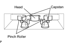
(a) Tape player / head cleaning:
(1) Raise the cassette door with your finger. Using a pencil or similar object, push in the guide.
(2) Using a cleaning pen or cotton applicator soaked in cleaner, clean the head surface, pinch rollers and capstans.
|
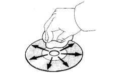
(b) CD cleaning: (1) If a disc is dirty, clean the disc by wiping the CD's underside radially with a soft cloth. NOTICE: Do not use a conventional record cleaner or anti-static preservative. |
|
3. OUTLINE OF AVC-LAN
(a) What is AVC-LAN?
AVC-LAN is the abbreviation, which stands for Audio Visual Communication-Local Area Network. This is a unified standard co-developed by 6 audio manufacturers associated with Toyota Motor Corporation.
The Unified standard covers signals, visual signals, signal for switch indication and communication signal. Radio receiver assembly and RSA (Rear Seat Audio) panel have a resistance (60-80 Ω) required for communication.
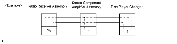
(b) Objectives
Recently the car audio system has been rapidly developed and functions have been changed drastically. The conventional system has been switched to the multi-media type such as a navigation system. At the same time, the level of customers needs to audio has been upgraded. This lies behind this standardization.
The concrete objectives are explained below.
(1) Step1: When products by different manufacturers were combined together, there used to be a case that malfunction occurred such as sound did not come out. This problem has been resolved by standardization of signals.
(2) Step2: Various types of after market products have been able to add or replace freely.
(3) Step3: Because of the above step2, each manufacturer has become able to concentrate on developing products in their strongest field. This has enabled many types of products to be provided inexpensively.
(4) Step4: In general, a new product developed by one particular manufacturer could not be used due to a lack of compatibility with other manufacturers products. Because of this new standard, users can enjoy many compatible products from different manufacturer anytime they went.
(c) The above descriptions are the objectives to introduce AVC-LAN. By this standardization, development of new products will no longer cause systematic errors.
HINT:
- When +B short or GND short is detected in AVC-LAN circuit, communication stops. And audio system does not function normally.
- When audio system is not equipped with a navigation system, audio head unit is the master unit. When audio system is equipped with a navigation system, multi-display is the master unit.
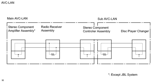
- This system has 2 kinds of AVC-LAN, Main AVC-LAN and Sub AVC-LAN.
- Stereo component controller assembly panel works as a master using AVC-LAN circuit has a diagnosis function.
-
The car audio system using AVC-LAN circuit has a diagnosis function.
(w/ Navigation system
![2006 MY LX470 [05/2005 - ]; NAVIGATION: NAVIGATION SYSTEM: AVC-LAN Circuit](../../../../stylegraphics/info.gif "2006 MY LX470 [05/2005 - ]; NAVIGATION: NAVIGATION SYSTEM: AVC-LAN Circuit") )
)
-
Each product has its own specified number called physical address. Numbers are also allotted to each function in one product, which are called logical address.
4. DIAGNOSIS CODE LIST
HINT:
w/ Navigation system
(a) Physical address: 190 Radio receiver assembly
HINT:
*1: It may be stored when the ignition switch is turned 1 min. again after engine start.
*2: It may be stored when the ignition switch is turned again after engine start.
*3: When 210 sec. has passed after pulling out the power supply connector of the master component with the ignition switch in ACC or ON, this code is stored.
|
Logical address |
DTC |
Diagnosis item |
Diagnosis content |
Countermeasure and inspected parts |
|---|---|---|---|---|
|
01 (Communication Control) |
21 |
ROM Error |
Error is detected in internal ROM. |
Replace radio receiver assembly. |
|
01 (Communication Control) |
22 |
RAM Error |
Error is detected in internal RAM. |
Replace radio receiver assembly. |
|
01 *1 (Communication Control) |
D6 |
Absence of Master |
Component in which this code is recorded has been disconnected from system with ignition in ACC or ON. Or, when this code was recorded, radio receiver assembly was disconnected. |
|
|
01 *2 (Communication Control) |
D8 |
NO Response to Connection Check |
Component shown by auxiliary code is or had been disconnected from system after engine start. D9 |
|
|
01 *1 (Communication Control) |
D9 |
Last Mode Error |
Component operated (sounds and / or images were provided) before engine stop is or has been disconnected with ignition switch in ACC or ON. |
|
|
01 (Communication Control) |
DA |
NO Response to ON / OFF Instruction |
No response is identified when changing mode (audio and visual mode change). Detected when sound and picture does not change by button operation. |
|
|
01 *1 (Communication Control) |
DB |
Mode status Error |
Dual alarm is detected. |
|
|
01 *3 (Communication Control) |
DC |
Transmission Error |
Transmission to component shown by auxiliary code has been failed. (Detecting this DTC does not necessarily mean actual failure.) |
|
|
01 *2 (Communication Control) |
DD |
Master Reset (Momentary Interruption) |
After engine is started, radio receiver assembly was disconnected from system. |
|
|
01 *2 (Communication Control) |
DE |
Slave Reset (Momentary Interruption) |
After engine is started, slave component was disconnected from system. |
|
|
01 *3 (Communication Control) |
DF |
Master Error |
Due to defective of radio receiver assembly, master function is switched to audio equipment. Error occurs in communication between sub-master (audio) and radio receiver assembly. |
|
|
01 (Communication Control) |
E0 |
Registration Completion Instruction Error |
"Registration Completion Instruction" command from radio receiver assembly cannot be received. |
|
|
01 *1 (Communication Control) |
E1 |
Audio processor ON error |
While source equipment is operating, AMP output is stopped. |
|
|
01 (Communication Control) |
E2 |
ON / OFF Instruction Parameter Request Transmission |
Error occurs in ON / OFF controlling command from radio receiver assembly. |
|
|
01 (Communication Control) |
E3 |
Registration Request Transmission |
Registration Request command is output from slave component. Receiving Connection Check Instruction, Registration Request command is output from sub-master component. |
|
|
01 (Communication Control) |
E4 |
Plural Frame Abort |
Plural frame transmission is aborted. |
|
|
60 (Radio receiver assembly) |
43 |
AM Tuner Error |
Abnormal condition is detected in AM tuner. Inspect radio receiver assembly. |
Replace radio receiver assembly. |
|
60 (Radio receiver assembly) |
44 |
FM Tuner Error |
Abnormal condition is detected in FM tuner. |
Replace radio receiver assembly. |
|
61 (Cassette switch) |
40 |
Mechanical or Media Error |
Malfunction due to mechanical failure is identified. Or, cassette tape is cut or entangled. |
Inspect cassette tape. |
|
61 (Cassette switch) |
41 |
EJECT Malfunction |
Malfunction due to mechanical failure. |
Replace radio receiver assembly. |
|
63 (In-dash CD auto Changer) |
42 |
No Disc Readout |
Disc cannot be read. |
Inspect CD. |
|
63 (In-dash CD auto Changer) |
44 |
CD Error |
Error is detected in CD auto changer. |
Replace radio receiver assembly. |
|
63 (In-dash CD auto Changer) |
45 |
EJECT Error |
CD cannot be ejected. |
Replace radio receiver assembly. |
|
63 (In-dash CD auto Changer) |
47 |
CD High Temp. |
High temperature is detected in CD auto changer. |
Replace radio receiver assembly. |
|
63 (In-dash CD auto Changer) |
48 |
CD Excess Current |
Excess current is applied in CD auto changer. |
Replace radio receiver assembly. |
(b) Physical address: 440 Stereo component amplifier
HINT:
*1: Even if no failure is detected, it may be stored depending on the battery condition or voltage for starting engine.
*2: It may be stored when the ignition switch is turned 1 min. again after start.
*3: It may be stored when the ignition switch is again after engine start.
*4: When 210 sec. has passed after pulling out the power supply connector of the master component with the ignition switch in ACC or ON, this code is stored.
|
Logical address |
DTC |
Diagnosis item |
Diagnosis content |
Countermeasure and inspected parts |
|---|---|---|---|---|
|
01 (Communication Control) |
21 |
ROM Error |
Abnormal condition of ROM is detected. |
Replace stereo component amplifier. |
|
01 (Communication Control) |
22 |
RAM Error |
Abnormal condition of RAM is detected. |
Replace stereo component amplifier. |
|
01 (Communication Control) |
D6 *1 |
Absence of Master |
Component in which this code is recorded has been disconnected from system with ignition in ACC or ON. Or, when this code was recorded, radio receiver assembly was disconnected. |
|
|
01 *6 (Communication Control) |
D7 |
Connection Check Error |
Component in which this code is recorded has been disconnected from system after engine start. Or, when this code was recorded, radio receiver assembly was disconnected. |
|
|
01 (Communication Control) |
DC *2 |
Transmission Error |
Transmission to component shown by auxiliary code has been failed. (This code does not necessarily mean actual failure.) |
If same auxiliary code is recorded in other component(s), check harness for power supply and communication system of components shown by sub code. |
|
01 (Communication Control) |
DD *3 |
Master Reset (Momentary Interruption) |
After engine is started, radio receiver assembly was disconnected from system. |
|
|
01 (Communication Control) |
DF *4 |
Master Error |
Due to defective condition of component with a display, master function is switched to audio equipment. Error occurs in communication between sub-master (audio) and master component. |
|
|
01 (Communication Control) |
E0 *1 |
Registration Completion Instruction Error |
"Registration Completion Instruction" command from radio receiver assembly cannot be received. |
Since this DTC is provided for engineering purposes, it may be detected when no actual failure exists. |
|
01 (Communication Control) |
E1 *1 |
Audio processor ON error |
While source equipment is operating, AMP output is stopped. |
|
|
01 (Communication Control) |
E2 |
ON / OFF Instruction Parameter Error |
Error is detected in ON / OFF control command from radio receiver assembly. |
Replace radio receiver assembly. |
|
01 (Communication Control) |
E3 |
Registration Request Transmission |
|
Since this DTC is provided for engineering purposes, it may be detected when no actual failure exists. |
|
01 (Communication Control) |
E4 |
Plural Frame Abort |
Plural frame transmission is aborted. |
Since this DTC is provided for engineering purposes, it may be detected when no actual failure exists. |
(c) Physical address: 1F4 RSA Panel (Main AVC-LAN)
HINT:
*1:Even if no failure is detected, it may be stored depending on the battery condition or voltage for starting an engine.
*2: It may be stored when the ignition switch is turned 1 min. again after engine start.
*3: It may be stored when the ignition switch is turned again after engine start.
*4: When 210 sec. has passed after pulling out the power supply connector of the master component with the ignition switch in ACC or ON, this code is stored.
|
Logical address |
DTC |
Diagnosis item |
Diagnosis content |
Countermeasure and inspected parts |
|---|---|---|---|---|
|
01 (Communication Control) |
D6 *1 |
Absence of Master |
Component in which this code is recorded has been disconnected from system with ignition in ACC or ON. Or, when this code was recorded, radio receiver assembly was disconnected. |
|
|
01 *6 (Communication Control) |
D7 |
Connection Check Error |
Component in which this code is recorded has been disconnected from system after engine start. Or, when this code was recorded, radio receiver assembly was disconnected. |
|
|
01 (Communication Control) |
DC *2 |
Transmission Error |
Transmission to component shown by auxiliary code has been failed. (This code does not necessarily mean actual failure.) |
If same auxiliary code is recorded in other component(s), check harness for power supply and communication system of components shown by sub code. |
|
01 (Communication Control) |
DD *3 |
Master Reset (Momentary Interruption) |
After engine is started, radio receiver assembly was disconnected from system. |
|
|
01 (Communication Control) |
DF *4 |
Master Error |
Due to defective of component with a display, master function is switched to audio equipment. Error occurs in communication between sub-master (audio) and master component. |
|
|
01 (Communication Control) |
E0 *1 |
Registration Completion Instruction Error |
"Registration Completion Instruction" command from radio receiver assembly cannot be received. |
Since this DTC is provided for engineering purposes, it may be detected when no actual failure exists. |
|
01 (Communication Control) |
E3 |
Registration Request Transmission |
|
Since this DTC is provided for engineering purposes, it may be detected when no actual failure exists. |
|
01 (Communication Control) |
E4 |
Plural Frame Abort |
Plural frame transmission is aborted. |
Since this DTC is provided for engineering purposes, it may be detected when no actual failure exists. |
(d) Physical address: 16A, 16C RSA Panel (stereo component controller assembly) (Sub AVC-LAN)
HINT:
*1: It may be stored when the ignition switch is turned 1 min. again after start.
*2: It may be stored when the ignition switch is turned again after start.
*3: When 210 sec. has passed after pulling out the power supply connector of the master component with the ignition switch in ACC or ON, this code is stored.
|
Logical address |
DTC |
Diagnosis item |
Diagnosis content |
Countermeasure and inspected parts |
|---|---|---|---|---|
|
01 *2 (Communication Control) |
D8 |
No Response to Connection Check |
Component shown by auxiliary code is or had been disconnected from system after engine start. D9 |
|
|
01 *2 (Communication Control) |
D9 |
Last Mode Error |
Component operated (sounds and / or images were provided) before engine stop is or has been disconnected with ignition switch in ACC or ON. |
|
|
01 (Communication Control) |
DA |
No Response to ON / OFF Instruction |
No response is identified when changing mode (audio and visual mode change). Detected when sound and picture does not change by button operation. |
|
|
01 *1 (Communication Control) |
DB |
Mode Status Error |
Dual alarm is detected. |
|
|
01 *3 (Communication Control) |
DC |
Transmission Error |
Transmission to component shown by auxiliary code has been failed. (Detecting this DTC does not necessarily mean actual failure.) |
|
|
01 *2 (Communication Control) |
DE |
Slave Reset (Momentary Interruption) |
After engine is started, slave component was disconnected from system. |
|
|
01 (Communication Control) |
E4 |
Plural Frame Abort |
Plural frame transmission is aborted. |
Since this DTC is provided for engineering purposes, it may be detected when no actual failure exists. |
(e) Physical address: 250DVD Auto Player (disc player changer)
HINT:
*1: Even if no failure is detected, this code may be stored depending on the battery condition or starting an engine.
*2: This code may be stored when the ignition switch is turned again 1 min. after engine start.
*3: This code may be stored when the ignition switch is turned again after engine start.
*4: When 210 sec. has passed after pulling out the power supply connector of the master component with the ignition switch in ACC or ON, this code is stored.
|
Logical address |
DTC |
Diagnosis item |
Diagnosis content |
Countermeasure and inspected parts |
|---|---|---|---|---|
|
01 (Communication Control) |
D6 *1 |
Absence of Master |
Component in which this code is recorded has been disconnected from system with ignition in ACC or ON. Or, when this code was recorded, stereo component controller assembly was disconnected. |
|
|
01 (Communication Control) |
D7 |
Communication Check Error |
Component in which this code is recorded is was disconnected from system after engine start. Or, when recorded this code, stereo component controller assembly was disconnected. |
|
|
01 *4 (Communication Control) |
DC |
Transmission Error |
Transmission to component shown by sub-code has been failed. (Detecting this DTC does not necessarily mean actual failure.) |
|
|
01 (Communication Control) |
DD *3 |
Master Reset (Momentary Interruption) |
After engine is started, radio receiver assembly assembly was disconnected from system. |
|
|
01 (Communication Control) |
DF *4 |
Master Error |
Due to defective condition of component with a display, master function is switched to audio equipment. Error occurs in communication between sub-master (audio) and master component. |
|
|
01 (Communication Control) |
E0 *1 |
Registration Completion Instruction Error |
"Registration Completion Instruction" command from master cannot be received. |
Since this DTC is provided for engineering purposes, it may be detected when no actual failure exists. |
|
01 (Communication Control) |
E2 |
ON / OFF Instruction Parameter Error |
Error is detected in ON / OFF control command from disc player changer. |
Replace DVD player. |
|
01 (Communication Control) |
E3 |
Registration Request Transmission |
|
Since this DTC is provided for engineering purposes, it may be detected when actual exists. |
|
01 (Communication Control) |
E4 |
Multiple Frame Abort |
Multiple frame transmission is aborted. |
Since this DTC is provided for engineering purposes, it may be detected when no actual failure exists. |
|
01 (Communication Control) |
22 |
RAM Error |
Abnormal condition of RAM is detected. |
Replace disc player changer. |
|
45 (DVD) |
44 |
DVD Error |
Error is detected in disc player changer. |
Replace radio and player. |
|
45 (DVD) |
45 |
EJECT Error |
Disk cannot be ejected. |
Check for foreign matter in disc player changer. |
|
45 (DVD) |
46 |
Disc crack |
A crack and dirt are in a disc. |
Inspect disc. |
|
45 (DVD) |
47 |
DVD High Temp |
High temperature is detected in disc player changer. |
Do not stop the operation for a period od time. |
|
45 (DVD) |
48 |
DVD Excess Current |
Excess current malfunction in insertion / ejection. |
Replace disc player changer. |
|
45 (DVD) |
50 |
A Malfunction in insertion / ejection |
Operating malfunction in insertion / ejection. |
Replace disc player changer. |
|
45 (DVD) |
51 |
A malfunction in switching disc |
Operating malfunction in switching disc. |
Replace disc player changer. |

|

|