-
All conditions below are detected 500 times or more continuously
(1 trip detection logic):
- No signal from speed sensor SP2 is input to ECM while 4 pulses of No. 1 vehicle speed sensor signal are sent
- Vehicle speed is 9 km/h (5.6 mph) or more for at least 4 sec.
- PNP switch is OFF
- Transfer position is not neutral (4WD)
| Last Modified: 4-30-2014 | 6.6 C | Doc ID: RM0000012TD005X |
| Model Year: 2006 | Model: LX470 | Prod Date Range: [05/2005 - ] |
| Title: A750F AUTOMATIC TRANSMISSION: AUTOMATIC TRANSMISSION SYSTEM: P0722; Output Speed Sensor Circuit No Signal; 2006 MY LX470 [05/2005 - ] | ||
|
DTC |
P0722 |
Output Speed Sensor Circuit No Signal |
DESCRIPTION
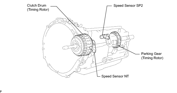
The speed sensor SP2 detects the rotation speed of the transmission output shaft and sends signals to the ECM. The ECM determines the vehicle speed based on these signals. AC voltage is generated in the speed sensor SP2 coil as the parking gear mounted on the rear planetary gear assembly rotates, and this voltage is sent to the ECM. The parking gear on the rear planetary gear is used as the timing rotor for this sensor. The gear shift point and lock-up timing are controlled by the ECM based on the signals from this vehicle speed sensor and the throttle position sensor signal.
|
DTC No. |
DTC Detection Condition |
Trouble Area |
|---|---|---|
|
P0722 |
|
|
|
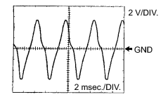
1. Reference: Inspect using an oscilloscope. Check the waveform of the ECM connector. Standard voltage: Refer to illustration.
|
|
MONITOR DESCRIPTION
The output speed sensor SP2 monitors the output shaft speed. The ECM controls the gear shift point and the lock-up timing based on the signals from the output speed sensor SP2 and throttle position sensor.
If the ECM detects no signal from the output shaft speed sensor SP2 even while the vehicle is moving, the ECM will conclude that the output shaft speed sensor SP2 is malfunctioning. The ECM will illuminate the MIL and set the DTC.
MONITOR STRATEGY
|
Related DTCs |
P0722: Speed sensor SP2/Verify pulse input |
|
Required sensors/Components |
Speed sensor SP2 |
|
Frequency of operation |
Continuous |
|
Duration |
500 output shaft revolution |
|
MIL operation |
Immediate |
|
Sequence of operation |
None |
TYPICAL ENABLING CONDITIONS
|
The monitor will run whenever the following DTCs are not present. |
P500: VSS P0748: Trans Solenoid (range) |
|
Vehicle speed range (4 sec. or more) |
9 km/h (5.6 mph) or more |
|
NSW switch |
OFF |
|
Transfer neutral switch |
OFF |
TYPICAL MALFUNCTION THRESHOLDS
|
No output speed sensor pulse input during 4 vehicle speed sensor pulse input |
500 times or more |
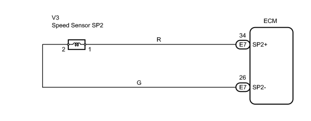
WIRING DIAGRAM
INSPECTION PROCEDURE
HINT:
Using the intelligent tester's DATA LIST allows switch, sensor, actuator and other item values to be read without removing any parts. Reading the DATA LIST early in troubleshooting is one way to save time.
NOTICE:
In the table below, the values listed under "Normal Condition" are reference values. Do not depend solely on these reference values when deciding whether a part is faulty or not.
- Warm up the engine.
- Turn the ignition switch OFF.
- Connect the intelligent tester to the CAN VIM. Then connect the CAN VIM to the DLC3.
- Turn the ignition switch ON.
- Turn the intelligent tester ON.
- Enter the following menus: DIAGNOSIS / ENHANCED OBD II / DATA LIST.
- Follow the instructions on the tester and read the DATA LIST.
|
Item |
Measurement Item/ Range (Display) |
Normal Condition |
Diagnostic Note |
|---|---|---|---|
|
SPD (SP2) |
Output shaft speed/ Min.: 0 km/h (0 mph) Max.: 255 km/h (158 mph) |
Vehicle stopped: 0 km/h (0 mph) (output shaft speed is equal to vehicle speed) |
- |
HINT:
-
SPD (SP2) is always 0 while driving:
Open or short in the sensor or circuit.
-
SPD (SP2) value displayed on the tester is much lower than the actual vehicle speed:
Sensor trouble, improper installation, or intermittent connection trouble of the circuit.
PROCEDURE
|
1. |
INSPECT SPEED SENSOR INSTALLATION |
|
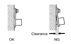
(a) Check the speed sensor SP2 installation. OK: Installation bolt is tightened properly and there is no clearance between the sensor and transmission case. |
|
| NG |

|
|

|
2. |
INSPECT SPEED SENSOR SP2 |
|
(a) Disconnect the V3 sensor connector from the transmission. |
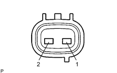
|
(b) Measure the resistance of the sensor.
Standard resistance:
|
Tester Connection |
Condition |
Specified Condition |
|---|---|---|
|
1 - 2 |
20°C (68°F) |
560 to 680 Ω |
| NG |
|
|
|
3. |
CHECK WIRE HARNESS (SPEED SENSOR - ECM) |
(a)
Check wire harness
![2006 MY LX470 [05/2005 - ]; INTRODUCTION: HOW TO TROUBLESHOOT ECU CONTROLLED SYSTEMS: ELECTRONIC CIRCUIT INSPECTION PROCEDURE](../../../../stylegraphics/info.gif "2006 MY LX470 [05/2005 - ]; INTRODUCTION: HOW TO TROUBLESHOOT ECU CONTROLLED SYSTEMS: ELECTRONIC CIRCUIT INSPECTION PROCEDURE") .
.
| NG |
|
| OK |
|

|

|