| Last Modified: 4-30-2014 | 6.6 G | Doc ID: RM0000013FB005X |
| Model Year: 2006 | Model: LX470 | Prod Date Range: [05/2005 - ] |
| Title: A750F AUTOMATIC TRANSMISSION: CLUTCH DRUM AND INPUT SHAFT ASSEMBLY: INSPECTION; 2006 MY LX470 [05/2005 - ] | ||
INSPECTION
|
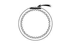
1. INSPECT REAR CLUTCH DISC (a) Replace all discs if one of the following problems is present: 1) a disc, plate or flange is worn or burnt, 2) the lining of a disc is peeled off or discolored, or 3) grooves or printed numbers have even a little bit of damage. NOTICE: Before assembling new discs, soak them in ATF for at least 15 minutes. |
|
|
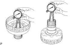
2. INSPECT REVERSE CLUTCH HUB SUB-ASSEMBLY (a) Using a caliper gauge, measure the inside diameter of the reverse clutch hub bushing. Standard drum bushing: 35.812 to 35.837 mm (1.4099 to 1.4109 in.) Maximum drum bushing: 35.887 mm (1.4129 in.)
|
|
|
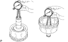
3. INSPECT FORWARD CLUTCH HUB SUB-ASSEMBLY (a) Using a caliper gauge, measure the inside diameter of the forward clutch hub bushing. Standard drum bushing: 26.037 to 26. 062 mm (1.0251 to 1.0261 in.) Maximum drum bushing: 26.112 mm (1.0280 in.)
|
|
|
4. INSPECT FORWARD MULTIPLE DISC CLUTCH DISC (a) Replace all discs if one of the following problems is present: 1) a disc, plate or flange is worn or burnt, 2) the lining of a disc is peeled off or discolored, or 3) grooves or printed numbers have even a little bit of damage. NOTICE: Before assembling new discs, soak them in ATF for at least 15 minutes. |
|
|
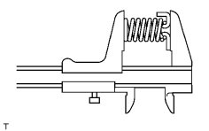
5. INSPECT FORWARD CLUTCH RETURN SPRING SUB-ASSEMBLY (a) Using a vernier caliper, measure the free length of the spring together with the spring seat. Standard free length: 26.74 mm (1.053 in.) |
|
|
6. INSPECT DIRECT CLUTCH DISK (a) Replace all discs if one of the following problems is present: 1) a disc, plate or flange is worn or burnt, 2) the lining of a disc is peeled off or discolored, or 3) grooves or printed numbers have even a little bit of damage. NOTICE: Before assembling new discs, soak them in ATF for at least 15 minutes. |
|
|
7. INSPECT REVERSE CLUTCH RETURN SPRING SUB-ASSEMBLY (a) Using a vernier caliper, measure the free length of the spring together with the spring seat. Standard free length: 21.04 mm (0.828 in.) |
|
|
8. INSPECT DIRECT CLUTCH RETURN SPRING SUB-ASSEMBLY (a) Using a vernier caliper, measure the free length of the spring together with the spring seat. Standard free length: 19.51 mm (0.768 in.) |
|
|
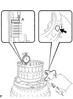
9. INSPECT PACK CLEARANCE OF DIRECT CLUTCH (a) Using a dial gauge, measure the moving distance (distance A) of the clutch flange at both ends across a diameter while blowing air from the oil hole as shown in the illustration, and calculate the average. Pack clearance: 0.5 to 0.8 mm (0.020 to 0.031 in.) NOTICE: Install a selective flange (3.4 mm (0.134 in.)) when measuring the moving distance (shaded area in the illustration.) HINT: Flange moving distance A = 0.26 to 1.14 mm (0.010 to 0.045 in.) Pack clearance = Flange moving distance A - 0.05 mm (0.002 in.) (b) If the pack clearance is outside the standard, select and install a clutch flange that makes the pack clearance within the standard. Standard flange thickness:
|
|
10. INSPECT PACK CLEARANCE OF REVERSE CLUTCH
(a) Using a dial gauge, measure the reverse clutch piston stroke (distance A) and the moving distance (distance B) of the reverse flange at the both ends across a diameter while blowing air (392 kPa, 4 kgf/cm 2 , 57 psi) from the oil hole as shown in the illustration, and calculate the average.
Pack clearance:
0.5 to 0.8 mm (0.020 to 0.031 in.)
NOTICE:
Install a selective flange (3.3 mm (0.130 in.)) when measuring the moving distance (shaded area in the illustration.)
HINT:
Piston stroke A = 1.05 to 2.15 mm (0.041 to 0.085 in.)
Flange moving distance B = 0.72 to 1.08 mm (0.029 to 0.043 in.)
Pack clearance = Piston stroke A to Flange moving distance B to 0.06 mm (0.002 in.)
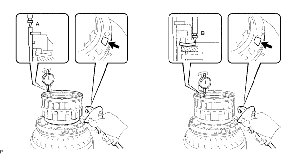
(b) If the pack clearance is outside the standard, select and install a clutch flange that makes the pack clearance within the standard.
Standard flange thickness:
|
No. |
Thickness |
No. |
Thickness |
|
0 |
2.8 mm (0.110 in.) |
6 |
3.4 mm (0.134 in.) |
|
1 |
2.9 mm (0.114 in.) |
7 |
3.5 mm (0.138 in.) |
|
2 |
3.0 mm (0.118 in.) |
8 |
3.6 mm (0.142 in.) |
|
3 |
3.1 mm (0.122 in.) |
9 |
3.7 mm (0.146 in.) |
|
4 |
3.2 mm (0.126 in.) |
A |
3.8 mm (0.150 in.) |
|
5 |
3.3 mm (0.130 in.) |
- |
- |
|
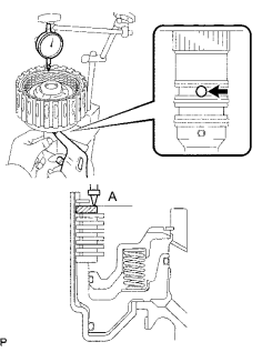
11. INSPECT PACK CLEARANCE OF FORWARD CLUTCH (a) Using a dial gauge, measure the moving distance (distance A) of the clutch flange at boths end across a diameter while blowing air from the oil hole as shown in the illustration, and calculate the average. Standard pack clearance: 0.6 to 0.9 mm (0.024 to 0.354 in.) NOTICE: Install a selective flange (3.4 mm (0.134 in.)) when measuring the moving distance (shaded area in the illustration.) HINT: Flange moving distance A = 0.26 to 1.36 mm (0.010 to 0.054 in.) Pack clearance = Flange moving distance A to 0.01 mm (0.0003 in.) (b) If the pack clearance is outside the standard, select and install a clutch flange that makes the pack clearance within the standard. Standard flange thickness:
|
|

|

|