| Last Modified: 4-30-2014 | 6.6 J | Doc ID: RM0000017CE003X |
| Model Year: 2006 | Model: LX470 | Prod Date Range: [05/2005 - ] |
| Title: PARK ASSIST / MONITORING: REAR VIEW MONITOR SYSTEM: Display Signal Circuit between Television Camera ECU and Multi-display; 2006 MY LX470 [05/2005 - ] | ||
|
Display Signal Circuit between Television Camera ECU and Multi-display |
DESCRIPTION
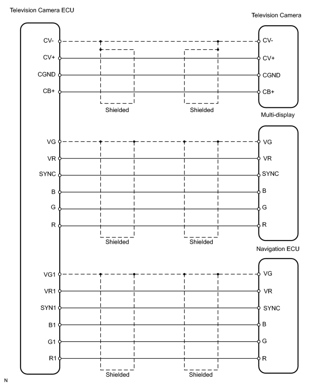
- This is the display signal circuit from the multi-display controller sub-assembly to the multi-display assembly.
WIRING DIAGRAM
INSPECTION PROCEDURE
PROCEDURE
|
1. |
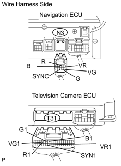
CHECK WIRE HARNESS (NAVIGATION ECU - TELEVISION CAMERA ECU) |
|
(a) Disconnect the N3 and T31 ECU connectors. |
|
(b) Measure the resistance according to the value(s) in the table below.
Standard resistance:
|
Tester Connection |
Specified Condition |
|---|---|
|
N3-2 (R) -T31-15 (R1) |
Below 1 Ω |
|
N3-7 (G) - T31-14(G1) |
Below 1 Ω |
|
N3-3 (B) -T31-13 (B1) |
Below 1 Ω |
|
N3-8 (SYNC) - T31-34 (SYN1) |
Below 1 Ω |
|
N3-1 (VR) - T31-33 (VR1) |
Below 1 Ω |
|
N3-6 (VG) -T31-16 (VG1) |
Below 1 Ω |
|
N3-2 (R) - Body ground |
10 kΩ or higher |
|
N3-7 (G) - Body ground |
10 kΩ or higher |
|
N3-3 (B) - Body ground |
10 kΩ or higher |
|
N3-8 (SYNC) - Body ground |
10 kΩ or higher |
|
N3-1 (VR) - Body ground |
10 kΩ or higher |
| NG |

|
|

|
2. |
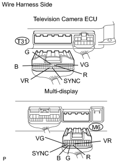
CHECK WIRE HARNESS (TELEVISION CAMERA ECU - MULTI-DISPLAY) |
|
(a) Disconnect the T31 ECU connector. |
|
(b) Disconnect the M6 display connector.
(c) Measure the resistance according to the value(s) in the table below.
Standard resistance:
|
Tester Connection |
Specified Condition |
|---|---|
|
T31-10 (R) - M6-24 (R) |
Below 1 Ω |
|
T31-11 (G) - M6-25 (G) |
Below 1 Ω |
|
T31-12 (B) - M6-26 (B) |
Below 1 Ω |
|
T31-31 (SYNC) - M6-27 (SYNC) |
Below 1 Ω |
|
T31-32 (VR) - M6-23 (VR) |
Below 1 Ω |
|
T31-9 (VG) - M6-28 (VG) |
Below 1 Ω |
|
T31-10 (R) - Body ground |
10 kΩ or higher |
|
T31-11 (G) - Body ground |
10 kΩ or higher |
|
T31-12 (B) - Body ground |
10 kΩ or higher |
|
T31-31 (SYNC) - Body ground |
10 kΩ or higher |
|
T31-32 (VR) - Body ground |
10 kΩ or higher |
| NG |
|
|
|
3. |
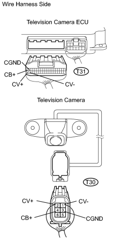
CHECK WIRE HARNESS (TELEVISION CAMERA ECU - TELEVISION CAMERA) |
|
(a) Disconnect the T31 ECU connector. |
|
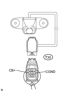
(b) Disconnect the T30 camera connector.
(c) Measure the resistance according to the value(s) in the table below.
Standard resistance:
|
Tester Connection |
Specified Condition |
|---|---|
|
T31-20 (CB+) - T30-4 (CB+) |
Below 1 Ω |
|
T31-19 (CGND) - T30-3 (CGND) |
Below 1 Ω |
|
T31-40 (CV+) - T30-2 (CV+) |
Below 1 Ω |
|
T31-39 (CV-) - T30-1 (CV-) |
Below 1 Ω |
|
T31-20 (CB+) - Body ground |
10 kΩ or higher |
|
T31-19 (CGND) - Body ground |
10 kΩ or higher |
|
T31-40 (CV+) - Body ground |
10 kΩ or higher |
|
T31-39 (CV-) - Body ground |
10 kΩ or higher |
| NG |
|
|
|
4. |
INSPECT TELEVISION CAMERA ECU |
|
(a) Measure the voltage according to the value(s) in the table below. Standard:
|
|
| NG |
|
| OK |
|
PROCEED TO NEXT CIRCUIT INSPECTION SHOWN IN PROBLEM SYMPTOMS TABLE |

|

|