| Last Modified: 4-30-2014 | 6.6 J | Doc ID: RM0000017KW003X |
| Model Year: 2006 | Model: LX470 | Prod Date Range: [05/2005 - ] |
| Title: PARK ASSIST / MONITORING: REAR VIEW MONITOR SYSTEM: AVC-LAN Circuit; 2006 MY LX470 [05/2005 - ] | ||
|
AVC-LAN Circuit |
DESCRIPTION
- Each unit of the "REAR VIEW MONITOR SYSTEM" connected with AVC-LAN (communication bus) transfers the signal of each switch by communication.
- When short to +B or short to ground occurs in this AVC-LAN, the "REAR VIEW MONITOR SYSTEM" will not function normally as the communication is discontinued.
WIRING DIAGRAM
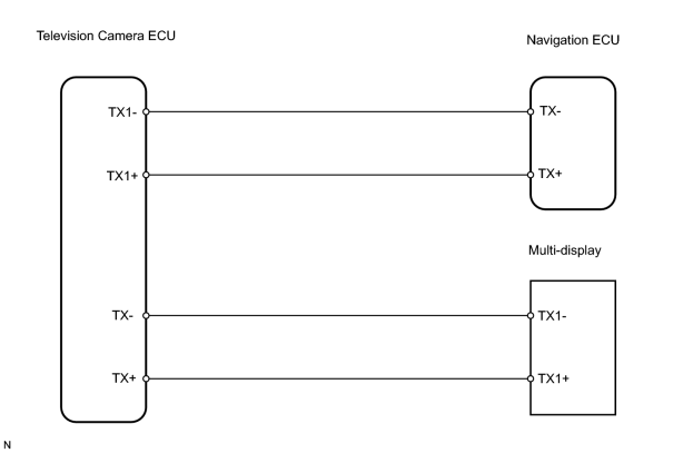
INSPECTION PROCEDURE
PROCEDURE
|
1. |
CHECK WIRE HARNESS (TELEVISION CAMERA ECU - NAVIGATION ECU) |
|
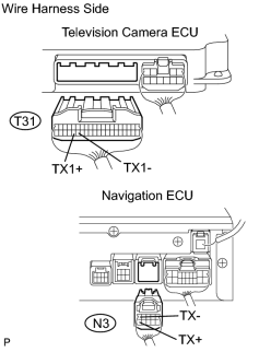
(a) Disconnect the T31 and N3 ECU connectors. |
|
(b) Measure the resistance according to the value(s) in the table below.
Standard resistance:
|
Tester Connection |
Specified Condition |
|---|---|
|
T31-36 (TX1+) - N3-5 (TX+) |
Below 1 Ω |
|
T31-35 (TX1-) - N3-10 (TX-) |
Below 1 Ω |
|
T31-36 (TX1+) - Body ground |
10 kΩ or higher |
|
T31-35 (TX1-) - Body ground |
10 kΩ or higher |
| NG |

|
|

|
2. |
CHECK WIRE HARNESS (TELEVISION CAMERA ECU - MULTI-DISPLAY) |
|
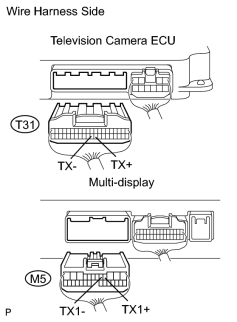
(a) Disconnect the T31 ECU connector. |
|
(b) Disconnect the M5 display connector.
(c) Measure the resistance according to the value(s) in the table below.
Standard resistance:
|
Tester Connection |
Specified Condition |
|---|---|
|
T31-29 (TX+) - M5-4(TX1+) |
Below 1 Ω |
|
T31-30 (TX-) - M5-5 (TX1-) |
Below 1 Ω |
|
T31-29 (TX+) - Body ground |
10 kΩ or higher |
|
T31-30 (TX-) - Body ground |
10 kΩ or higher |
| NG |
|
| OK |
|
PROCEED TO NEXT CIRCUIT INSPECTION SHOWN IN PROBLEM SYMPTOMS TABLE |

|

|