| Last Modified: 4-30-2014 | 6.6 U | Doc ID: RM00000185G000X |
| Model Year: 2006 | Model: LX470 | Prod Date Range: [05/2005 - ] |
| Title: ENGINE IMMOBILISER: ENGINE IMMOBILISER SYSTEM: TERMINALS OF ECU; 2006 MY LX470 [05/2005 - ] | ||
TERMINALS OF ECU
1. CHECK TRANSPONDER KEY ECU ASSEMBLY

(a) Disconnect the T27 ECU connector.
(b) Measure the resistance and voltage of the wire harness side connector.
|
Symbols (Terminal No.) |
Wiring Color |
Terminal Description |
Condition |
Specified Condition |
|---|---|---|---|---|
|
GND (T27-14) - Body ground |
W-B - Body ground |
Ground |
Always |
Below 1 Ω |
|
+B (T27-1) - GND (T27-14) |
L-W - W-B |
Power source supply |
Always |
10 to 14 V |
|
IG (T27-2) - GND (T27-14) |
B-R - W-B |
Ignition power supply |
Ignition switch ON |
10 to 14 V |
|
Ignition switch OFF |
Below 1 V |
|||
|
KSW (T27-10) - GND (T27-14) |
R-B - W-B |
Unlock warning switch |
No key in ignition key cylinder |
10 kΩ or higher |
|
Key inserted |
Below 1 Ω |
|||
|
CTY (T27-4) - GND (T27-14) |
R-Y - W-B |
Driver side courtesy switch |
Driver side door closed |
10 kΩ or higher |
|
Driver side door open |
Below 1 Ω |
- If the result is not as specified, there may be a malfunction on the wire harness side.
(c) Reconnect the T27 ECU connector.
(d) Measure the voltage of the connector.
|
Symbols (Terminal No.) |
Wiring Color |
Terminal Description |
Condition |
Specified Condition |
|---|---|---|---|---|
|
KSW (T27-10) - GND (T27-14) |
R-B - W-B |
Unlock warning switch |
No key in ignition key cylinder |
10 to 14 V |
|
Key inserted |
Below 1 V |
|||
|
VC5 (T27-8) - GND (T27-14) |
Y - W-B |
Power source of transponder key amplifier |
No key in ignition key cylinder |
Below 1 V |
|
Key inserted |
4.6 to 5.4 V |
|||
|
TXCT (T27-12) - GND (T27-14) |
V-G - W-B |
Transponder key amplifier communication signal |
No key in ignition key cylinder |
Below 1 V |
|
Key inserted |
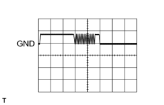
Pulse generation (see waveform 1) |
|||
|
CODE (T27-11) - GND (T27-14) |
L-B - W-B |
Transponder key amplifier communication signal |
No key in ignition key cylinder |
Below 1 V |
|
Key inserted |
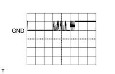
Pulse generation (see waveform 2) |
|||
|
EFIO (T27-6) - GND (T27-14) |
W - W-B |
ECM output signal |
Ignition switch OFF |
Below 1 V |
|
Ignition switch ON |
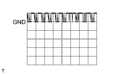
Pulse generation (see waveform 3) |
|||
|
EFII (T27-7) - GND (T27-14) |
Y - W-B |
ECM input signal |
Ignition switch OFF |
10 to 14 V |
|
Within 3 seconds after starter operates and initial combustion occurs, or within 3seconds after ignition switch first turned on (IG) after battery disconnected and connected. |
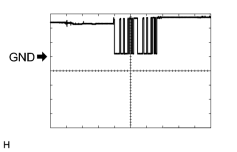
Pulse generation (see waveform 4) |
|||
|
IND (T27-3) - GND (T27-14) |
G-R - W-B |
Security indicator light signal |
Engine immobiliser system is unset |
Below 1 V |
|
Engine immobiliser system is set |
Pulse generation |
|||
|
CTY (T27-4) - GND (T27-14) |
R-Y - W-B |
Driver side courtesy switch |
Driver side door closed |
10 to 14 V |
|
Driver side door open |
Below 1 V |
- If the result is not as specified, the ECU may have a malfunction
(e) Inspect using an oscilloscope.
|
(1) Waveform 1 (Reference)
|
|
|
(2) Waveform 2 (Reference)
|
|
|
(3) Waveform 3 (Reference)
|
|
|
(4) Waveform 4 (Reference)
|
|
2. CHECK ECM
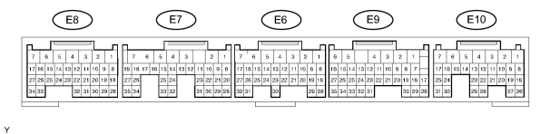
(a) Measure the resistance and voltage of the connectors.
|
Symbols (Terminal No.) |
Wiring Color |
Terminal Description |
Condition |
Specified Condition |
|---|---|---|---|---|
|
E1 (E6-1) - Body ground |
BR- Body ground |
Ground |
Always |
Below 1 Ω |
|
BATT (E10-3) - E1 (E6-1) |
B-R - BR |
Battery (for measuring battery voltage and for ECM memory) |
Always |
10 to 14 V |
|
+BM (E10-7) - E1 (E6-1) |
Y-B - BR |
Power source of ECM |
Ignition switch OFF |
Below 1 V |
|
Ignition switch ON |
10 to 14 V |
|||
|
+B (E10-1) - E1 (E6-1) |
B-Y -BR |
Power source of ECM |
Ignition switch OFF |
Below 1 V |
|
Ignition switch ON |
10 to 14 V |
|||
|
+B2 (E10-2) - E1 (E6-1) |
B-Y - BR |
Power source of ECM |
Ignition switch OFF |
Below 1 V |
|
Ignition switch ON |
10 to 14 V |
|||
|
IGSW (E10-9) - E1 (E6-1) |
B-R -BR |
Ignition power supply of ECM |
Ignition switch OFF |
Below 1 V |
|
Ignition switch ON |
10 to 14 V |
|||
|
IMI (E9-16) - E1 (E6-1) |
W-BR |
Transponder key ECU input signal |
Ignition switch OFF |
Below 1 V |
|
Ignition switch ON |
Pulse generation (see waveform 1) |
|||
|
IMO (E9-15) - E1 (E6-1) |
Y-BR |
Transponder key ECU output signal |
Ignition switch OFF |
10 to 14 V |
|
Within 3 seconds after starter operates and initial combustion occurs, or within 3seconds after ignition switch first turned on (IG) after battery disconnected and connected. |
Pulse generation (see waveform 2) |
- If the result is not as specified, the ECM may have a malfunction.
(b) Inspect using an oscilloscope.
|
(1) Waveform 1 (Reference)
|
|
|
(2) Waveform 1 (Reference)
|
|

|

|