| Last Modified: 4-30-2014 | 6.6 A | Doc ID: RM000001890001X |
| Model Year: 2006 | Model: LX470 | Prod Date Range: [05/2005 - ] |
| Title: 2UZ-FE CHARGING: GENERATOR: DISASSEMBLY; 2006 MY LX470 [05/2005 - ] | ||
DISASSEMBLY
1. REMOVE GENERATOR REAR END COVER
|
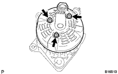
(a) Remove the 3 nuts and end cover. |
|
|
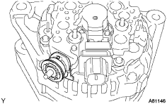
(b) Remove the terminal insulator. |
|
2. REMOVE GENERATOR BRUSH HOLDER ASSEMBLY
|
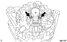
(a) Remove the 2 screws and brush holder. |
|
3. REMOVE GENERATOR PULLEY
|
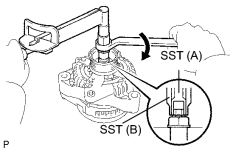
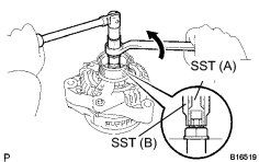
(a) Hold SST (A) with a torque wrench, and tighten SST (B) clockwise to the specified torque. SST: 09820-63011 Torque: 39 N·m {400 kgf·cm, 29ft·lbf} |
|
(b) Check that SST (A) is secured to the rotor shaft.
|
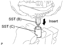
(c) Mount SST (C) in a vise. |
|
(d) Insert SST (B) into SST (C), and attach the pulley nut to SST (C).
|
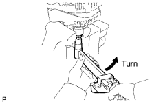
(e) To loosen the pulley nut, turn SST (A) in the direction shown in the illustration. NOTICE: To prevent damage to the rotor shaft, do not loosen the pulley nut more than one half of a turn. |
|
(f) Remove the generator from SST (C).
|
(g) Turn SST (B), and remove SST (A and B). |
|
(h) Remove the pulley nut and pulley.
4. REMOVE GENERATOR COIL ASSEMBLY
|
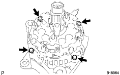
(a) Remove the 4 bolts. |
|
|
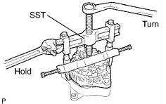
(b) Using SST, remove the coil assembly. SST: 09950-40011 09951-04020 09952-04010 09953-04020 09954-04010 09955-04071 09957-04010 09958-04011 |
|
(c) Remove the generator washer.
5. REMOVE GENERATOR ROTOR ASSEMBLY

|

|