| Last Modified: 4-30-2014 | 6.6 A | Doc ID: RM000001891001X |
| Model Year: 2006 | Model: LX470 | Prod Date Range: [05/2005 - ] |
| Title: 2UZ-FE CHARGING: GENERATOR: REASSEMBLY; 2006 MY LX470 [05/2005 - ] | ||
REASSEMBLY
1. INSTALL GENERATOR ROTOR ASSEMBLY
|
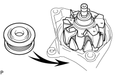
(a) Place the drive end frame on the pulley. |
|
(b) Install the rotor to the drive end frame.
2. INSTALL GENERATOR COIL ASSEMBLY
|
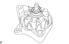
(a) Place the generator washer on the rotor. |
|
|
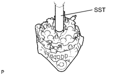
(b) Using SST and a press, slowly press in the coil assembly. SST: 09285-76010 |
|
|
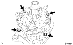
(c) Install the 4 bolts. Torque: 5.8 N·m {59 kgf·cm, 51in·lbf} |
|
3. INSTALL GENERATOR PULLEY
|
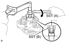
(a) Install the pulley to the rotor shaft by tightening the pulley nut by hand. |
|
(b) Hold SST (A) with a torque wrench, and tighten SST (B) clockwise to the specified torque.
SST: 09820-63011
Torque:
39 N·m {400 kgf·cm, 29ft·lbf}
(c) Check that SST (A) is secured to the pulley shaft.
|
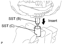
(d) Mount SST (C) in a vise. |
|
(e) Insert SST (B) into SST (C), and attach the pulley nut to SST (C).
|
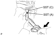
(f) To torque the pulley nut, turn SST (A) in the direction shown in the illustration. Torque: 111 N·m {1,125 kgf·cm, 81ft·lbf} |
|
(g) Remove the generator from SST (C).
|
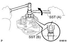
(h) Turn SST (B), and remove SST (A and B). |
|
4. INSTALL GENERATOR BRUSH HOLDER ASSEMBLY
|
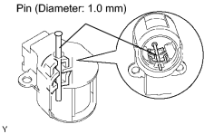
(a) While pushing the 2 brushes toward the inside of the brush holder, insert a pin (φ1.0 mm (0.039 in.)) into the brush holder hole. |
|
|
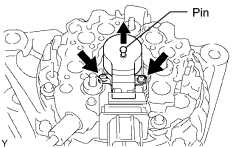
(b) Install the generator brush holder with the 2 screws. Torque: 1.8 N·m {18 kgf·cm, 16in·lbf} |
|
(c) Pull out the pin from the generator brush holder.
5. INSTALL GENERATOR REAR END COVER
|
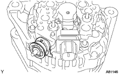
(a) Install the terminal insulator to the generator rectifier end frame. NOTICE: Pay attention the mounting orientation of the terminal insulator. |
|
|
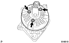
(b) Install the end cover with the 3 nuts. Torque: 4.6 N·m {47 kgf·cm, 41in·lbf} |
|

|

|