- Tilt and telescopic manual switch circuit
- Tilt and telescopic ECU
- Wire harness
| Last Modified: 4-30-2014 | 6.6 C | Doc ID: RM0000018A8003X |
| Model Year: 2006 | Model: LX470 | Prod Date Range: [05/2005 - ] |
| Title: STEERING COLUMN: POWER TILT AND POWER TELESCOPIC STEERING COLUMN SYSTEM: B2603; Tilt and Telescopic Manual Switch Circuit Malfunction; 2006 MY LX470 [05/2005 - ] | ||
|
DTC |
B2603 |
Tilt and Telescopic Manual Switch Circuit Malfunction |
DESCRIPTION
The different voltage value is input to the tilt and telescopic ECU by operating the manual switch. Then the tilt and telescopic ECU judges which motor and which direction the tilt motor or the telescopic motor should be moved based on the voltage value.
|
DTC No. |
DTC Detection Condition |
Trouble Area |
|---|---|---|
|
B2603 |
The abnormal voltage value which is not within the specification is input to the tilt and telescopic ECU when being operated with the manual switch. |
|
WIRING DIAGRAM
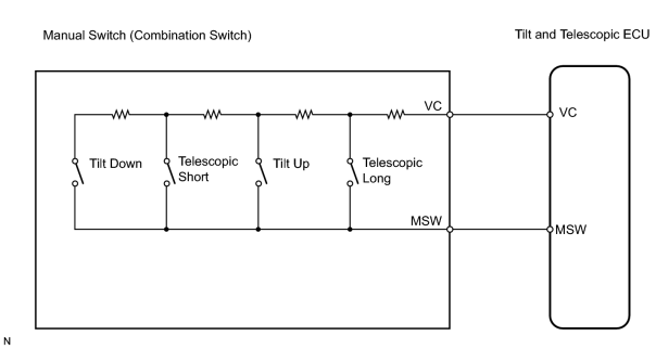
INSPECTION PROCEDURE
PROCEDURE
|
1. |
CHECK TILT AND TELESCOPIC MANUAL SWITCH |
|
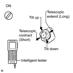
(a) When using the intelligent tester. (1) Connect the intelligent tester (with CAN VIM) to the DLC3. (2) Turn ignition switch ON and push the intelligent tester main switch ON. (3) Select DATA LIST mode on the intelligent tester. (4) Read the voltages on the tester screen when operating the manual switch. |
|
|
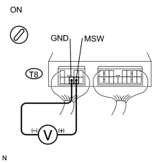
(b) When not using the intelligent tester. (1) Remove the tilt and telescopic ECU with the connector still connected. (2) Measure the voltage between terminals MSW and GND of the T8 ECU connector when operating the manual switch. |
|
Standard voltage:
Result
|
Manual Switch Position |
Specified Condition |
|---|---|
|
Neutral position |
0.00 to 0.20 V |
|
Tilt UP |
1.30 to 1.70 V |
|
Tilt DOWN |
0.30 to 0.50 V |
|
Telescopic SHORT |
0.65 to 0.95 V |
|
Telescopic LONG |
2.05 to 2.75 V |
|
Result |
Proceed to |
|---|---|
|
Switch voltages in all directions are within the standard. |
A |
|
Switch voltage in a certain direction is out of the standard. |
B |
|
Switch voltages in all directions are out of the standard. |
C |
| A |

|
| B |
|
|

|
2. |
CHECK TILT AND TELESCOPIC ECU (VC VOLTAGE) |
|
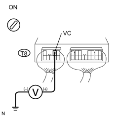
(a) Remove the ECU with the connectors still connected. |
|
(b) Measure the voltage between terminal VC of the T8 ECU connector and body ground.
Standard voltage:
4.5 to 5.5 V
| NG |
|
|
|
3. |
INSPECT TILT AND TELESCOPIC MANUAL SWITCH |
|
(a) Disconnect the combination switch connector. |
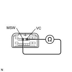
|
(b) Measure the resistance between terminals VC and MSW of the combination switch connector when operating the manual switch.
Standard resistance:
|
Switch position |
Resistance |
|---|---|
|
Tilt UP |
352 to 368 Ω |
|
Tilt DOWN |
1,950 to 2,030 Ω |
|
Telescopic SHORT |
774 to 806 Ω |
|
Telescopic LONG |
156 to 164 Ω |
| NG |
|
|
|
4. |
CHECK WIRE HARNESS (ECU - SWITCH) |
| NG |
|
| OK |
|
PROCEED TO NEXT CIRCUIT INSPECTION SHOWN ON PROBLEM SYMPTOMS TABLE |

|

|