| Last Modified: 4-30-2014 | 6.6 U | Doc ID: RM0000018GV000X |
| Model Year: 2006 | Model: LX470 | Prod Date Range: [05/2005 - ] |
| Title: THEFT DETERRENT: THEFT DETERRENT SYSTEM: TERMINALS OF ECU; 2006 MY LX470 [05/2005 - ] | ||
TERMINALS OF ECU
1. CHECK THEFT WARNING ECU ASSEMBLY
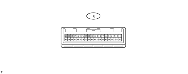
(a) Measure the resistance and voltage of the connector.
|
Symbols (Terminal No.) |
Wiring Color |
Terminal Description |
Condition |
Specified Condition |
|---|---|---|---|---|
|
E (T6-29) - Body ground |
W-B - Body ground |
Ground |
Always |
Below 1 Ω |
|
+B1 (T6-2) - Body ground |
LG - Body ground |
+B (ECU-B) power source |
Always |
10 to 14 V |
|
+B2 (T6-3) - Body ground |
L-W - Body ground |
Power source supply |
Always |
10 to 14 V |
|
IG (T6-10) - Body ground |
B-W - Body ground |
Ignition power supply |
Ignition switch OFF |
Below 1 V |
|
Ignition switch ON |
10 to 14 V |
|||
|
SH- (T6-1) - Body ground |
W - Body ground |
Security horn signal |
Security horn is sounding (Theft deterrent system is in alarm sounding state) |
Pulse generation |
|
HORN (T6-5) - E (T6-29) |
G-O - W-B |
Both vehicle horn signal outputs (low pitched and high pitched) |
Armed state |
10 to 14 V |
|
Alarm sounding state |
Below 1 V |
|||
|
KSW (T6-12) - E (T6-29) |
R-B - W-B |
Unlock warning switch signal input |
No key in ignition key cylinder |
10 kΩ or higher |
|
Key inserted in ignition key cylinder |
Below 1 Ω |
|||
|
REV (T6-23) - E (T6-29) |
B - W-B |
Engine revolution signal input |
Idling |
Pulse generation |
|
DSWH (T6-34) - E (T26-29) |
L-B - W-B |
Engine hood courtesy switch signal input |
Engine hood fully closed |
10 kΩ or higher |
|
Engine hood open |
Below 1 Ω |
- If the result is not specified, the ECU may have a malfunction.

|

|