| Last Modified: 4-30-2014 | 6.6 D | Doc ID: RM0000018H2000X |
| Model Year: 2006 | Model: LX470 | Prod Date Range: [05/2005 - ] |
| Title: THEFT DETERRENT: THEFT DETERRENT SYSTEM: DIAGNOSIS SYSTEM; 2006 MY LX470 [05/2005 - ] | ||
DIAGNOSIS SYSTEM
1. DESCRIPTION
(a) The theft warning ECU controls the vehicle's theft deterrent system functions. Theft deterrent system data can be read in the data link connector 3 (DLC3) of the vehicle. When the system seems to be malfunctioning, use the intelligent tester to check for malfunctions and perform repairs.
2. CHECK DLC3
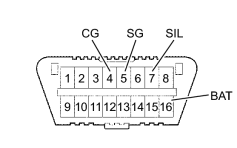
HINT:
The vehicle uses ISO 15765-4 communication protocol. The terminal arrangement of the DLC3 complies with SAE J1962 and matches the ISO 15765-4 format.
|
Symbols (Terminal No.) |
Terminal Description |
Condition |
Specified Condition |
|---|---|---|---|
|
SIL (7) - SG (5) |
Bus "+" line |
During transmission |
Pulse generation |
|
BAT (16) - Body ground |
Battery positive |
Always |
10 to 14 V |
|
CG (4) - Body ground |
Chassis ground |
Always |
Below 1 Ω |
|
SG (5) - Body ground |
Signal ground |
Always |
Below 1 Ω |
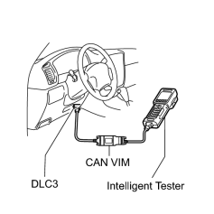
HINT:
Connect the cable of the intelligent tester (with CAN VIM) to the DLC3, turn the ignition switch ON and attempt to use the tester. If the screen displays the message UNABLE TO CONNECT TO VEHICLE, there is a problem either with the vehicle or with the tester.
- If communication is normal when the tester is connected to another vehicle, inspect the DLC3 of the original vehicle.
- If communication is still not possible when the tester is connected to another vehicle, the problem is probably in the tester itself. Consult the Service Department listed in the tester's instruction manual.

|

|