| Last Modified: 4-30-2014 | 6.6 J | Doc ID: RM0000018HA000X |
| Model Year: 2006 | Model: LX470 | Prod Date Range: [05/2005 - ] |
| Title: THEFT DETERRENT: THEFT DETERRENT SYSTEM: Security Horn Circuit; 2006 MY LX470 [05/2005 - ] | ||
|
Security Horn Circuit |
DESCRIPTION
When the theft deterrent system is activated, the relay in the ECU is turned ON and OFF at approximately 0.2 second intervals, causing the theft deterrent horn to sound (see the warning diagram below). In this condition, if any of the following operations are performed, the relay in the ECU is turned OFF, stopping the security horn from sounding:
- Unlock the driver door with key.
- Turn the ignition switch ON.
- Unlock the doors with the wireless door lock control system.
- Wait for approximately 60 seconds.
- Press the panic switch of the wireless door lock control system.
WIRING DIAGRAM
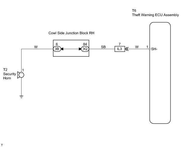
INSPECTION PROCEDURE
HINT:
When using the intelligent tester, start from *1. When not using the intelligent tester, start from *2.
PROCEDURE
|
1. |
PERFORM ACTIVE TEST USING INTELLIGENT TESTER (SECURITY HORN) *1 |
(a) Select the ACTIVE TEST, use the intelligent tester to generate a control command, and then check the security horn operation.
Theft warning ECU assembly:
|
Item |
Test Details |
Diagnostic Note |
|---|---|---|
|
SECURITY HORN2 |
Turns security horn ON / OFF |
- |
OK:
The security horn sounds or stops sounding in accordance with the tester command.
| OK |

|
PROCEED TO NEXT CIRCUIT INSPECTION SHOWN ON PROBLEM SYMPTOMS TABLE |
|

|
2. |
INSPECT SECURITY HORN ASSEMBLY *2 |
|
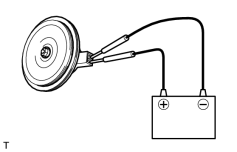
(a) Apply battery voltage to the horn and check the operation of the horn. OK:
|
|
| NG |
|
|
|
3. |
CHECK WIRE HARNESS (THEFT WARNING ECU ASSEMBLY - SECURITY HORN ASSEMBLY) |
(a) Disconnect the T6 ECU connector.
(b) Disconnect the T2 horn connector.
(c) Measure the resistance of the wire harness side connectors.
Standard resistance:
|
Tester Connection |
Specified Condition |
|---|---|
|
T6-1 (SH-) - T2-1 |
Below 1 Ω |
|
T6-1 (SH-) or T2-1 - Body ground |
10 kΩ or higher |
| NG |
|
| OK |
|
PROCEED TO NEXT CIRCUIT INSPECTION SHOWN ON PROBLEM SYMPTOMS TABLE |

|

|