| Last Modified: 4-30-2014 | 6.6 A | Doc ID: RM0000018IW001X |
| Model Year: 2006 | Model: LX470 | Prod Date Range: [05/2005 - ] |
| Title: 2UZ-FE INTAKE: VACUUM SWITCHING VALVE: REMOVAL; 2006 MY LX470 [05/2005 - ] | ||
REMOVAL
1.
DISCHARGE FUEL SYSTEM PRESSURE
![2006 MY LX470 [05/2005 - ]; 2UZ-FE FUEL: FUEL INJECTOR: REMOVAL+](../../../../stylegraphics/info.gif "2006 MY LX470 [05/2005 - ]; 2UZ-FE FUEL: FUEL INJECTOR: REMOVAL+")
2. DISCONNECT CABLE FROM NEGATIVE BATTERY TERMINAL
CAUTION:
Wait at least 90 seconds after disconnecting the cable from the negative (-) battery terminal to prevent airbag and seat belt pretensioner activation.
3.
DISCONNECT FUEL RETURN HOSE
4.
DISCONNECT FUEL MAIN HOSE
5.
DRAIN ENGINE COOLANT
6.
REMOVE V-BANK COVER SUB-ASSEMBLY
7.
REMOVE INTAKE AIR CONNECTOR PIPE
8. REMOVE INTAKE MANIFOLD ASSEMBLY
(a) Disconnect the connectors from the intake manifold.
(1) Disconnect the throttle position sensor and control motor connector.
(2) Disconnect the purge VSV connector.
(3) Disconnect 8 injector connectors.
(4) Disconnect the ECT sensor connector.
(5) Disconnect the 2 VSV connectors (for air injection system).
|
(b) Disconnect the hoses from the intake manifold. (1) Disconnect the vacuum hose from the fuel pressure regulator. (2) Disconnect the PCV hose from the PCV valve on the LH cylinder head. (3) Disconnect the purge line hose (from charcoal canister) from the purge VSV. (4) Disconnect the 2 vacuum hoses from the VSVs (for air injection system). |
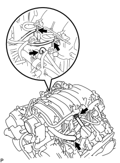
|
|
(c) Disconnect the 2 water by-pass hoses from the throttle body. |
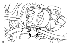
|
|
(d) Disconnect the 2 wire clamps from the wire clamps brackets on the RH delivery pipe. |
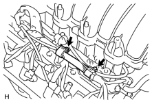
|
|
(e) Remove the 2 bolts holding the engine wire protector from the intake manifold and cylinder head. |
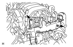
|
(f) Remove the 2 bolts and 2 ground cables from the RH and LH cylinder heads.
(g) Remove the bolt and throttle body cover bracket from the intake manifold.
|
(h) Disconnect the 2 engine wire clamps from the wire bracket and engine hanger. |
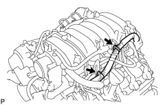
|
(i) Remove the bolt and wire bracket from the intake manifold.
|
(j) Remove the 6 bolts, 4 nuts, intake manifold assembly and 2 gaskets. |
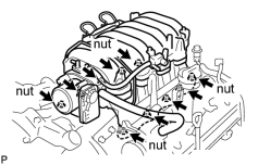
|
9. REMOVE VACUUM SWITCHING VALVE ASSEMBLY (for ACIS)
|
(a) Remove the bolt and VSV (for ACIS) from the intake manifold. |
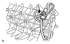
|

|

|