- Tire pressure monitor antenna
| Last Modified: 4-30-2014 | 6.6 C | Doc ID: RM0000018L9001X |
| Model Year: 2006 | Model: LX470 | Prod Date Range: [05/2005 - ] |
| Title: TIRE AND WHEEL: TIRE PRESSURE WARNING SYSTEM: C2121/21,...,C2185/85; No Signal from Transmitter ID1 in Main Mode; 2006 MY LX470 [05/2005 - ] | ||
|
DTC |
C2121/21 |
No Signal from Transmitter ID1 in Main Mode |
|
DTC |
C2122/22 |
No Signal from Transmitter ID2 in Main Mode |
|
DTC |
C2123/23 |
No Signal from Transmitter ID3 in Main Mode |
|
DTC |
C2124/24 |
No Signal from Transmitter ID4 in Main Mode |
|
DTC |
C2125/25 |
No Signal from Transmitter ID5 in Main Mode |
|
DTC |
C2131/31 |
No Signal from Transmitter ID1 in 2nd Mode |
|
DTC |
C2132/32 |
No Signal from Transmitter ID2 in 2nd Mode |
|
DTC |
C2133/33 |
No Signal from Transmitter ID3 in 2nd Mode |
|
DTC |
C2134/34 |
No Signal from Transmitter ID4 in 2nd Mode |
|
DTC |
C2135/35 |
No Signal from Transmitter ID5 in 2nd Mode |
|
DTC |
C2181/81 |
Transmitter ID1 not Received (Test Mode DTC) |
|
DTC |
C2182/82 |
Transmitter ID2 not Received (Test Mode DTC) |
|
DTC |
C2183/83 |
Transmitter ID3 not Received (Test Mode DTC) |
|
DTC |
C2184/84 |
Transmitter ID4 not Received (Test Mode DTC) |
|
DTC |
C2185/85 |
Transmitter ID5 not Received (Test Mode DTC) |
DESCRIPTION
The tire pressure monitor valve sub-assembly constantly sends radio waves to the tire pressure monitor ECU. If the battery for the tire pressure monitor valve sub-assembly is depleted, or if the tire pressure antenna is defective or comes off, a DTC will be output. DTCs C2121/21 to C2125/25 and C2131/31 to C2135/35 can only be deleted by the tester. DTCs C2181/81 to C2185/85 can be deleted when the transmitter sends a forced transmission signal or the test mode ends. DTCs C2181/81 to C2185/85 are output only in the test mode.
|
DTC No. |
DTC Detecting Condition |
Trouble Area |
|---|---|---|
|
C2121/21 C2122/22 C2123/23 C2124/24 C2125/25 C2131/31 C2132/32 C2133/33 C2134/34 C2135/35 |
These DTCs are detected when no signals are received for 51 minutes or more, after a vehicle speed of 5 mph (8 km/h) or more is detected and no signals are received for 12 minutes or more. |
|
|
C2181/81 C2182/82 C2183/83 C2184/84 C2185/85 |
Malfunction in the transmitting/receiving circuit |
|
HINT:
It is necessary to perform the procedure to identify the tire pressure monitor valve sub-assembly that is malfunctioning because it cannot be identified by the output DTC.
WIRING DIAGRAM
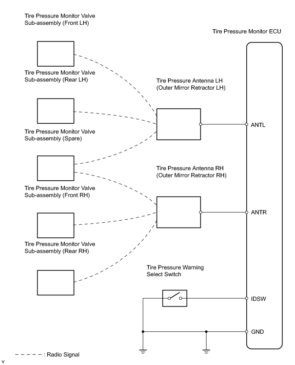
INSPECTION PROCEDURE
NOTICE:
It is necessary to register an ID code after replacing the tire pressure monitor valve sub-assembly and/or the tire pressure monitor ECU
![2006 MY LX470 [05/2005 - ]; TIRE AND WHEEL: TIRE PRESSURE WARNING SYSTEM: REGISTRATION](../../../../stylegraphics/info.gif "2006 MY LX470 [05/2005 - ]; TIRE AND WHEEL: TIRE PRESSURE WARNING SYSTEM: REGISTRATION") .
.
HINT:
Set the tire pressure to the specified value.
PROCEDURE
|
1. |
CHECK TIRE PRESSURE WARNING LIGHT*1 |
(a) Turn the ignition switch ON.
(b) Check the tire pressure warning light.
Result
|
Condition |
Proceed to |
|---|---|
|
Does not blink |
A |
|
Comes on and goes off repeatedly at 0.5 second intervals |
B |
| B |

|
|

|
2. |
CLEAR DTC |
(a)
Clear the DTC
.
|
|
3. |
CHECK DTC |
(a)
Check for DTC
.
|
Result |
Proceed to |
|---|---|
|
DTCs C2121/21, C2122/22, C2123/23, C2124/24 and C2125/25 are all output |
A |
|
DTCs C2131/31, C2132/32, C2133/33, C2134/34 and C2135/35 are all output |
B |
|
DTC C2121/21, C2122/22, C2123/23, C2124/24 or C2125/25 is output |
C |
|
DTCs C2131/31, C2132/32, C2133/33, C2134/34 or C2135/35 is output |
D |
|
DTC is not output |
E |
| B |
|
| C |
|
| D |
|
| E |
|
|
|
4. |
CHECK TIRE PRESSURE WARNING SELECT SWITCH (MAIN POSITION) |
|
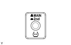
OK: Tire pressure warning select switch is set to "MAIN". HINT: If the tire pressure warning select switch is not set to "MAIN", set the tire pressure to the specified value and set the tire pressure warning select switch to "MAIN". Afterwards, perform forced transmission of the transmitter ID by rapidly reducing the pressure of all the tires and go to step *1. |
|
| NG |
|
|
|
5. |
CHECK TEST MODE DTC |
(a)
Check for test mode DTC
.
Result
|
Result |
Proceed to |
|---|---|
|
C2195/95 output |
A |
|
C2195/95 not output |
B |
| B |
|
|
|
6. |
CHECK WIRE HARNESS (ECU - ANTENNA) |
|
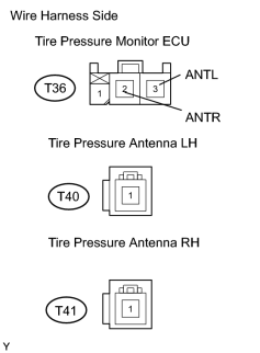
(a) Disconnect the T36 ECU connector. |
|
(b) Disconnect the T40 and T41 antenna connectors.
(c) Measure the resistance of the wire harness side connectors.
Standard resistance:
|
Tester Connection |
Specified Condition |
|---|---|
|
T36-3 (ANTL) - T40-1 |
Below 1 Ω |
|
T36-2 (ANTR) - T41-1 |
Below 1 Ω |
| NG |
|
|
|
7. |
REPLACE OUTER MIRROR RETRACTOR (TIRE PRESSURE ANTENNA) |
|
|
8. |
CHECK DTC |
(a)
Check for DTC
.
OK:
DTC is not output.
| OK |
|
|
|
9. |
CHECK WIRE HARNESS (ECU - SELECT SWITCH) |
|
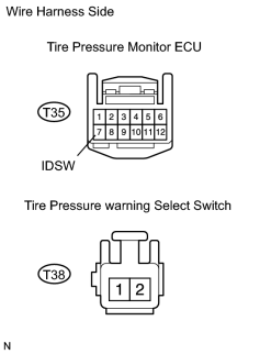
(a) Disconnect the T35 ECU connector. |
|
(b) Disconnect the T38switch connector.
(c) Measure the resistance of the wire harness side connectors.
Standard resistance:
|
Tester Connection |
Specified Condition |
|---|---|
|
T35-7 (IDSW) - T38-2 |
Below 1 Ω |
|
T35-7 (IDSW) - Body ground |
10 kΩ or higher |
|
T38-1 - Body ground |
Below 1 Ω |
| NG |
|
|
|
10. |
INSPECT TIRE PRESSURE WARNING SELECT SWITCH |
|
(a) Remove the select switch. |
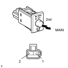
|
(b) Measure the resistance of the switch.
Standard resistance:
|
Tester Connection |
Switch Position |
Specified Condition |
|---|---|---|
|
1 - 2 |
MAIN |
10 kΩ or higher |
|
1 - 2 |
2nd |
Below 1 Ω |
| NG |
|
|
|
11. |
REPLACE TIRE PRESSURE MONITOR ECU |
|
|
12. |
CHECK DTC |
(a)
Check for DTC
.
OK:
DTC is not output.
| NG |
|
|
|
13. |
SET TIRE PRESSURE TO NORMAL VALUE |
(a) Set the tire pressure of all wheels (including the spare tire) to the specified value.
Standard pressure
|
Front |
Rear |
Spare |
|||
|---|---|---|---|---|---|
|
200 kPa (2.0 kgf/cm 2 , 29 psi) |
Trailer Towing |
220 kPa (2.2 kgf/cm 2 , 32 psi) |
Trailer Towing |
220 kPa (2.2 kgf/cm 2 , 32 psi) |
Trailer Towing |
|
220 kPa (2.2 kgf/cm 2 , 32 psi) |
240 kPa (2.4 kgf/cm 2 , 35 psi) |
240 kPa (2.4 kgf/cm 2 , 35 psi) |
|||
|
|
14. |
IDENTIFY TRANSMITTER CORRESPONDING TO DTC*2 |
(a)
Identify transmitter corresponding to DTC
.
|
|
15. |
INTERCHANGE TIRES |
|
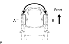
(a) Interchange tire "A" (with a defective tire pressure monitor valve sub-assembly) with tire "B" (with a normal one). |
|
HINT:
Perform this step if tire "A" (left front) is identified in step *2 above.
|
|
16. |
SET TIRE PRESSURE TO NORMAL VALUE |
(a) Set the tire pressure of all wheels (including the spare tire) to the specified value.
Standard pressure
|
Front |
Rear |
Spare |
|||
|---|---|---|---|---|---|
|
200 kPa (2.0 kgf/cm 2 , 29 psi) |
Trailer Towing |
220 kPa (2.2 kgf/cm 2 , 32 psi) |
Trailer Towing |
220 kPa (2.2 kgf/cm 2 , 32 psi) |
Trailer Towing |
|
220 kPa (2.2 kgf/cm 2 , 32 psi) |
240 kPa (2.4 kgf/cm 2 , 35 psi) |
240 kPa (2.4 kgf/cm 2 , 35 psi) |
|||
|
|
17. |
FORCIBLY TRANSMISSION OF TRANSMITTER ID |
|
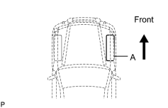
(a) Remove the valve core of tire "A", rapidly reduce the tire pressure, and perform forced transmission of the transmitter ID of the tire pressure monitor valve sub-assembly. |
|
|
|
18. |
CHECK DTC AGAIN |
(a)
Check for DTC
.
OK:
DTC is not output.
HINT:
- If a DTC is output, replace the identified tire pressure monitor valve sub-assembly.
- Before installing a new tire pressure monitor valve sub-assembly, read and write down its transmitter ID.
- Register the transmitter ID after replacement, and then set the tire pressure to the specified value.
| NG |
|
| OK |
|
|
19. |
CHECK TIRE PRESSURE WARNING SELECT SWITCH (2ND POSITION) |
|
OK: Tire pressure warning select switch is set to "2nd". HINT: If the tire pressure warning select switch is not set to "2nd", set the tire pressure to the specified value and set the tire pressure warning switch to "2nd". Afterward, perform forced transmission of the transmitter ID by rapidly reducing the pressure of all the tires (including the spare tire) and go to step *1. |
|
| OK |
|
| NG |
|

|

|