- Vehicle speed sensor
- Combination meter assembly
- Tire pressure monitor ECU
- Wire harness
| Last Modified: 4-30-2014 | 6.6 C | Doc ID: RM0000018LD001X |
| Model Year: 2006 | Model: LX470 | Prod Date Range: [05/2005 - ] |
| Title: TIRE AND WHEEL: TIRE PRESSURE WARNING SYSTEM: C2191/91; Vehicle Speed Signal Error (Test Mode DTC); 2006 MY LX470 [05/2005 - ] | ||
|
DTC |
C2191/91 |
Vehicle Speed Signal Error (Test Mode DTC) |
DESCRIPTION
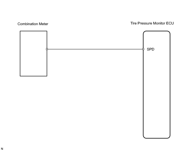
The tire pressure monitor ECU receives a speed signal from the combination meter. This DTC is stored upon entering test mode but erased when a vehicle speed signal of 12 mph (20 km/h) is detected for 3 seconds or more. The DTC is output only in test mode.
|
DTC No. |
DTC Detecting Condition |
Trouble Area |
|---|---|---|
|
C2191/91 |
Speed sensor circuit malfunction. |
|
WIRING DIAGRAM
INSPECTION PROCEDURE
NOTICE:
It is necessary to register an ID code after replacing the tire pressure monitor valve sub-assembly and/or the tire pressure monitor ECU
![2006 MY LX470 [05/2005 - ]; TIRE AND WHEEL: TIRE PRESSURE WARNING SYSTEM: REGISTRATION](../../../../stylegraphics/info.gif "2006 MY LX470 [05/2005 - ]; TIRE AND WHEEL: TIRE PRESSURE WARNING SYSTEM: REGISTRATION") .
.
HINT:
When not using the intelligent tester, go to step *1.
PROCEDURE
|
1. |
READ VALUE USING INTELLIGENT TESTER |
(a) Connect the intelligent tester (with CAN VIM) to the DLC3.
(b) Turn the ignition switch ON, and push the intelligent tester main switch ON.
(c) Select the item below in the DATA LIST, and read its value displayed on the intelligent tester.
(d) Check that the values indicated on the tester and the combination meter are the same.
Tire pressure monitor ECU
|
Item |
Measurement item / Range(Display) |
Normal Condition |
Diagnostic Note |
|---|---|---|---|
|
VEHICLE SPEED |
Vehicle speed reading / Min.: 0 km/h (0 mph) Max.: 255 km/h (158 mph) |
Actual vehicle speed |
Speed indicated on the combination meter |
OK:
Indicates actual speed.
| OK |

|
|

|
2. |
CHECK WIRE HARNESS (ECU - COMBINATION METER) *1 |
|
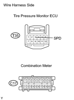
(a) Disconnect the C17 combination meter connector. |
|
(b) Disconnect the T35 ECU connector.
(c) Measure the resistance of the wire harness side connectors.
Standard resistance:
|
Tester Connection |
Specified Condition |
|---|---|
|
T35-3 (SPD) - C17-16 |
Below 1 Ω |
|
T35-3 (SPD) - Body ground |
10 kΩ or higher |
| NG |
|
|
|
3. |
INSPECT TIRE PRESSURE MONITOR ECU |
|
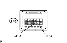
(a) Connect the T35 ECU connector. |
|
(b) Connect the C17 combination meter connector.
|
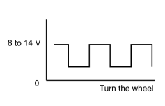
(c) Measure the voltage of the ECU as the front wheel is turned.
HINT: As the vehicle speed (wheel revolution speed) increases, a cycle of the waveform narrows. |
|
| NG |
|
| OK |
|

|

|