| Last Modified: 4-30-2014 | 6.6 J | Doc ID: RM0000018M1002X |
| Model Year: 2006 | Model: LX470 | Prod Date Range: [05/2005 - ] |
| Title: CRUISE CONTROL: CRUISE CONTROL SYSTEM: Cruise Control Switch Circuit; 2006 MY LX470 [05/2005 - ] | ||
|
Cruise Control Switch Circuit |
DESCRIPTION
This circuit carries the -/SET, +/RESUME and CANCEL signals (each voltage) to the ECM.
WIRING DIAGRAM
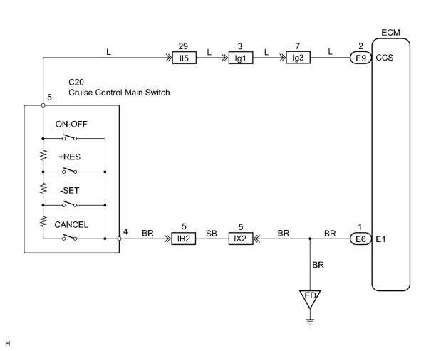
INSPECTION PROCEDURE
PROCEDURE
|
1. |
CHECK ECM (CCS VOLTAGE) |
|
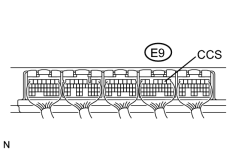
(a) Remove the ECM with the connector still connected. |
|
(b) Turn the ignition switch ON.
(c) Measure the voltage between terminal CCS of the E9 ECM connector and body ground, when each of the -/SET, +RES and CANCEL switches are turned ON.
Standard voltage:
|
Switch Position |
Specified Condition |
|---|---|
|
Neutral |
10 to 14 V |
|
+/RES |
2.3 to 4 V |
|
-/SET |
4.5 to 7.1 V |
|
CANCEL |
6.6 to 10.1 V |
| OK |

|
PROCEED TO NEXT CIRCUIT INSPECTION SHOWN IN PROBLEM SYMPTOMS TABLE |
|

|
2. |
INSPECT CRUISE CONTROL MAIN SWITCH |
|
(a)
Remove the steering wheel center pad
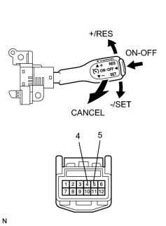
(b) Disconnect the control switch connector. (c) Measure the resistance between terminals 4 and 5 of the cruise control switch connector when the control switch is operated. Standard resistance:
(d) Check continuity between terminals 4 and 5 of the control switch connector when the main switch is held on and off. OK:
|
|
| NG |
|
|
|
3. |
CHECK WIRE HARNESS (CRUISE CONTROL MAIN SWITCH - ECM AND BODY GROUND) |
| NG |
|
|
|
4. |
CHECK CRUISE MAIN INDICATOR LIGHT |
(a)
Check CRUISE main indicator light
![2006 MY LX470 [05/2005 - ]; CRUISE CONTROL: CRUISE CONTROL SYSTEM: DIAGNOSIS SYSTEM](../../../../stylegraphics/info.gif "2006 MY LX470 [05/2005 - ]; CRUISE CONTROL: CRUISE CONTROL SYSTEM: DIAGNOSIS SYSTEM") .
.
| NG |
|
| OK |
|

|

|