| Last Modified: 4-30-2014 | 6.6 J | Doc ID: RM0000018NG002X |
| Model Year: 2006 | Model: LX470 | Prod Date Range: [05/2005 - ] |
| Title: AIR CONDITIONING: AIR CONDITIONING SYSTEM: IG Power Source Circuit; 2006 MY LX470 [05/2005 - ] | ||
|
IG Power Source Circuit |
DESCRIPTION
This is the power source for the A/C amplifier and servomotors, etc.
WIRING DIAGRAM
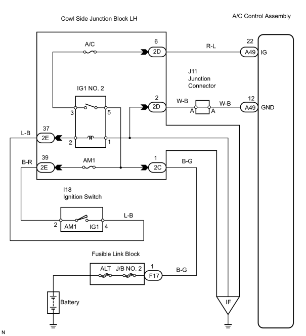
INSPECTION PROCEDURE
PROCEDURE
|
1. |
INSPECT FUSE |
(a) Remove the A/C and AM1 fuse from the cowl side junction block LH.
(b) Measure the resistance of the fuse.
Standard resistance:
Below 1 Ω
| NG |

|
|

|
2. |
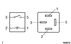
INSPECT IG1 NO. 2 RELAY |
|
(a) Remove the IG1 NO. 2 relay from the cowl side junction block LH. |
|
(b) Measure the resistance of the relay.
Standard resistance:
|
Tester Connection |
Specified Condition |
|---|---|
|
3 - 5 |
10 kΩ or higher |
|
3 - 5 |
Below 1 Ω (When battery voltage is applied to terminals 1 and 2) |
| NG |
|
|
|
3. |
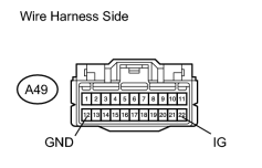
CHECK WIRE HARNESS AND CONNECTOR (AIR CONDITIONING AMPLIFIER - BODY GROUND) |
(a) Disconnect the A49 A/C amplifier connector.
|
(b) Measure the voltage and resistance of the wire harness side connector. Standard voltage:
Standard resistance:
|
|
| NG |
|
| OK |
|

|

|