| Last Modified: 4-30-2014 | 6.6 A | Doc ID: RM0000018O5002X |
| Model Year: 2006 | Model: LX470 | Prod Date Range: [05/2005 - ] |
| Title: POWER STEERING: POWER STEERING GEAR: REMOVAL; 2006 MY LX470 [05/2005 - ] | ||
REMOVAL
NOTICE:
Remove the steering wheel assembly before the steering gear removal, because there is possibility of breaking of the spiral cable.
1. DISCONNECT CABLE FROM NEGATIVE BATTERY TERMINAL
CAUTION:
Wait at least 90 seconds after disconnecting the cable from the negative (-) battery terminal to prevent airbag and seat belt pretensioner activation.
2. PLACE FRONT WHEELS FACING STRAIGHT AHEAD
3.
REMOVE STEERING WHEEL PAD
![2006 MY LX470 [05/2005 - ]; SUPPLEMENTAL RESTRAINT SYSTEM: STEERING PAD: REMOVAL+](../../../../stylegraphics/info.gif "2006 MY LX470 [05/2005 - ]; SUPPLEMENTAL RESTRAINT SYSTEM: STEERING PAD: REMOVAL+")
4.
REMOVE STEERING WHEEL ASSEMBLY
5. REMOVE NO. 1 ENGINE UNDER COVER
(a) Remove the 7 bolts.
6. REMOVE NO. 2 ENGINE UNDER COVER
(a) Remove the 6 bolts.
7.
DISCONNECT TIE ROD END SUB-ASSEMBLY LH
8. DISCONNECT TIE ROD END SUB-ASSEMBLY RH
HINT:
Use the same procedures described for the LH side.
9. REMOVE ENGINE OIL FILTER ASSEMBLY
(a) Disconnect the 2 clips and hoses.
(b) Remove the 2 bolts and nut with the bracket.
(c) Remove the O-ring.
10. DISCONNECT NO. 2 INTERMEDIATE SHAFT ASSEMBLY
HINT:
Turn the steering wheel fully to the right side.
11. DISCONNECT PRESSURE FEED TUBE ASSEMBLY
(a) Remove the union bolt, gasket and disconnect the pressure feed tube.
|
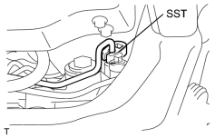
12. DISCONNECT RETURN TUBE ASSEMBLY (a) Using SST, disconnect the tube. SST: 09023-38401 |
|
|
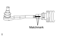
13. REMOVE TIE ROD END SUB-ASSEMBLY LH (a) Place matchmarks on the tie rod end and rack end. (b) Loosen the lock nut, and remove the tie rod end and lock nut. |
|
14. REMOVE TIE ROD END SUB-ASSEMBLY RH
HINT:
Use the same procedures described for the LH side.
|
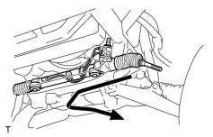
15. REMOVE POWER STEERING GEAR ASSEMBLY (a) Remove the 2 gear assembly set bolts, nuts and washers. (b) Slide the gear assembly to the right side, pull out the left side of the gear assembly from the member. |
|

|

|