| Last Modified: 4-30-2014 | 6.6 A | Doc ID: RM0000018O7002X |
| Model Year: 2006 | Model: LX470 | Prod Date Range: [05/2005 - ] |
| Title: POWER STEERING: POWER STEERING GEAR: REASSEMBLY; 2006 MY LX470 [05/2005 - ] | ||
REASSEMBLY
NOTICE:
When using a vise, do not overtighten it.
1. COAT PARTS INDICATED BY ARROWS WITH POWER STEERING FLUID OR MOLYBDENUM DISULFIDE LITHIUM BASE GREASE
|
2. INSTALL POWER STEERING GEAR HOUSING SUB-ASSEMBLY (a) Install SST to the rack. SST: 09631-00350 HINT: If necessary, scrape the burrs off the rack teeth end and burnish. (b) Coat SST with power steering fluid. (c) Install the rack into the rack housing. (d) Remove the SST. |
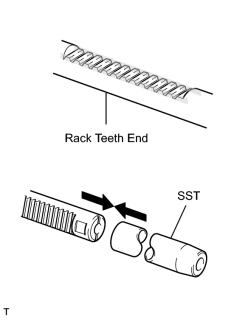
|
|
3. INSTALL POWER STEERING GEAR HOUSING OIL SEAL (a) Install SST to the steering rack opposite end. SST: 09631-00350 (b) Coat SST with power steering fluid. (c) Coat a new oil seal lip with power steering fluid. (d) Install the oil seal by pushing it onto the SST without tilting. NOTICE: Make sure to install the oil seal facing the correct direction. (e) Remove the SST. |
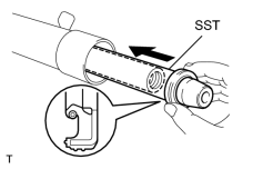
|
4. INSTALL SPACER AND CYLINDER END STOPPER
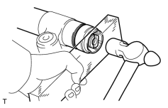
(a) Install the spacer.
(b) Coat a new O-ring with power steering fluid, and install it to the stopper.
(c) Using a wooden block and hammer, drive in the stopper until it is tightly installed.
NOTICE:
Be careful not to damage the O-ring.
|
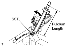
(d) Using SST, torque the stopper. SST: 09922-10010 Torque: 110 N·m {1,122 kgf·cm, 81ft·lbf} NOTICE: Use SST 09922-10010 in the direction shown in the illustration. HINT: Use a torque wrench with a fulcrum length of 380 mm (14.97 in.). |
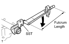
|
|
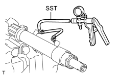
5. AIR TIGHTNESS TEST (a) Install SST to the unions of the rack housing. SST: 09631-12071 (b) Apply 53 kPa (400 mmHg, 15.75 in.Hg) of vacuum for about 30 seconds. (c) Check that there is no change in the vacuum. If there is change in the vacuum, check the installation of the oil seals. |
|
6. INSTALL CONTROL VALVE ASSEMBLY
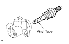
(a) Coat the teflon rings with power steering fluid.
(b) To prevent oil seal lip damage, wind vinyl tape on the serrated part of the control valve shaft.
(c) Push the valve assembly into the control valve housing.
NOTICE:
Be careful not to damage the teflon rings and oil seal lip.
|
(d) Coat a new O-ring with power steering fluid, and install it to the bearing guide nut. |
|
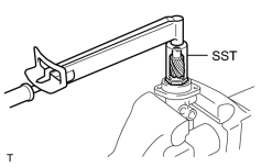
(e) Using SST, torque the nut.
SST: 09631-20060
Torque:
24.5 N·m {250 kgf·cm, 18ft·lbf}
NOTICE:
Be careful not to damage the oil seal lip.
|
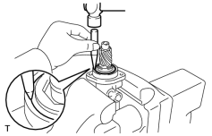
(f) Using a punch, stake the nut. |
|
7. INSTALL CONTROL VALVE HOUSING WITH CONTROL VALVE ASSEMBLY
(a) Coat a new O-ring with power steering fluid, and install it to the valve housing.
(b) Align the matchmarks on the valve housing and rack housing, and install the valve housing with the valve assembly to the rack housing.
(c) Torque the 2 bolts.
Torque:
18 N·m {180 kgf·cm, 13ft·lbf}
8. INSTALL POWER STEERING GEAR HOUSING OIL SEAL
9. INSTALL RACK GUIDE SUB-ASSEMBLY, RACK GUIDE SPRING AND RACK GUIDE SPRING CAP
(a) Apply sealant to 2 or 3 threads of the cap.
Sealant:
Toyota Genuine Adhesive 1344, Three Bond 1344 or Equivalent
(b) Temporarily install the cap.
10. ADJUST TOTAL PRELOAD
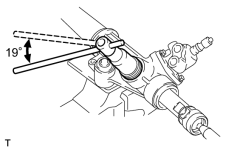
(a) To prevent the steering rack teeth from damaging the oil seal lip, temporarily install the RH and LH rack ends.
(b) Torque the rack guide spring cap.
Torque:
25 N·m {250 kgf·cm, 18ft·lbf}
(c) Return the cap 19°.
|
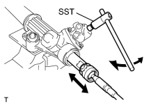
(d) Using SST, turn the control valve shaft right and left 1 or 2 times. SST: 09616-00011 |
|
(e) Loosen the cap until the rack guide spring is not functioning.
|
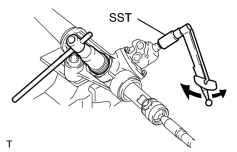
(f) Using SST and a torque wrench, tighten the cap until the preload is within specification. SST: 09616-00011 Standard preload (turning): Center area 1.8 to 2.2 (18.4 to 22.4 kgf*cm, 16.0 to 19.5 in.*lbf) End area 1.3 to 1.7 (13.3 to 17.3 kgf*cm, 11.5 to 15.0 in.*lbf) |
|
|
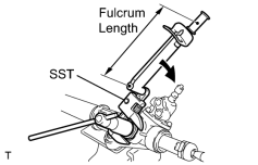
11. INSTALL RACK GUIDE SPRING CAP LOCK NUT (a) Apply sealant to 2 or 3 threads of the nut. Sealant: Toyota Genuine Adhesive 1344, Three Bond 1344 or Equivalent (b) Holding the rack guide spring cap rotating, and using SST, torque the nut. SST: 09922-10010 Torque: 52 N·m {520 kgf·cm, 38ft·lbf} NOTICE: Use SST 09922-10010 in the direction shown in the illustration. HINT: Use a torque wrench with a fulcrum length of 345 mm (14.97 in.). (c) Recheck the total preload. Standard preload (turning): Center area 1.8 to 2.2 (18.4 to 22.4 kgf*cm, 16.0 to 19.5 in.*lbf) End area 1.3 to 1.7 (13.3 to 17.3 kgf*cm, 11.5 to 15.0 in.*lbf) (d) Remove the RH and LH rack ends. |
|
12. INSTALL CLAW WASHER AND RACK END
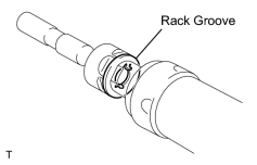
(a) Install a new washer, and temporarily tighten the rack end.
HINT:
Align the claws of the washer with the steering rack grooves.
|
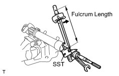
(b) Using a spanner to hold the steering rack steady, and using SST, torque the rack end. SST: 09922-10010 Torque: 99 N·m {1,014 kgf·cm, 74ft·lbf} NOTICE: Use SST 09922-10010 in the direction shown in the illustration. HINT: Use a torque wrench with a fulcrum length of 380 mm (13.58 in.). |
|
|
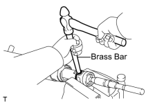
(c) Using a brass bar and hammer, stake the washer. NOTICE: Avoid any impact to the rack. |
|
(d) Use the same procedure described above for the other side.
13. INSTALL RACK BOOT, CLAMP AND CLIP
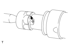
(a) Ensure that the tube hole is not clogged with grease.
HINT:
If the tube hole is clogged, the pressure inside the boot will change after it is assembled and the steering wheel is turned.
|
(b) Install the boot. NOTICE: Be careful not to damage or twist the boot. |
|
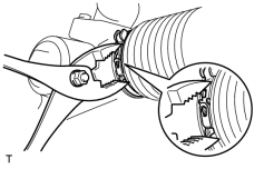
(c) Using pliers, tighten a new clamp, as shown in the illustration.
(d) Use the same procedure described above for the other side.
|
14. INSTALL TURN PRESSURE TUBE ASSEMBLY (a) Using SST, install the 2 tubes. SST: 09023-38201 Torque: 23 N·m {230 kgf·cm, 17ft·lbf} HINT:
|
|

|

|