| Last Modified: 4-30-2014 | 6.6 A | Doc ID: RM0000018QU002X |
| Model Year: 2006 | Model: LX470 | Prod Date Range: [05/2005 - ] |
| Title: PROPELLER SHAFT: FRONT PROPELLER SHAFT ASSEMBLY: REASSEMBLY; 2006 MY LX470 [05/2005 - ] | ||
REASSEMBLY
1. INSTALL UNIVERSAL JOINT SPIDER ASSEMBLY
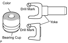
(a) Select the bearing according to whether or not there is a drill mark on the yoke section.
|
Yoke |
Bearing |
|---|---|
|
w/ Drill mark |
w/ Color mark (Red) |
|
No drill mark |
No color mark |
|
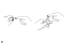
(b) Apply MP grease to a new spider and bearings. NOTICE: Be careful not to apply too much grease. |
|
|
(c) Fit the spider into the flange yoke. |
|
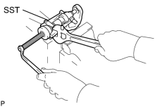
(d) Using SST, install the bearings on the spider.
SST: 09332-25010
|
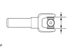
(e) Using SST, adjust both bearings so that the snap ring grooves are at maximum and equal in width. SST: 09332-25010 |
|
(f) Install 2 new snap rings of equal thickness which will allow 0 mm (0 in.) axial play.
HINT:
Do not reuse the snap rings.
Standard snap ring thickness :
|
Color |
Mark |
Thickness |
|---|---|---|
|
- |
1 |
2.28 to 2.30 mm (0.0898 to 0.0906 in.) |
|
- |
2 |
2.30 to 2.32 mm (0.0906 to 0.0913 in.) |
|
- |
- |
2.32 to 2.34 mm (0.0913 to 0.0921 in.) |
|
Brown |
- |
2.34 to 2.36 mm (0.0921 to 0.0929 in.) |
|
Blue |
- |
2.36 to 2.38 mm (0.0929 to 0.0937 in.) |
|
- |
6 |
2.38 to 2.40 mm (0.0937 to 0.0945 in.) |
|
- |
7 |
2.40 to 2.42 mm (0.0945 to 0.0953 in.) |
|
- |
8 |
2.42 to 2.44 mm (0.0953 to 0.0961 in.) |
|
- |

|
2.44 to 2.46 mm (0.0961 to 0.0969 in.) |
|
- |
10 |
2.46 to 2.48 mm (0.0969 to 0.0976 in.) |
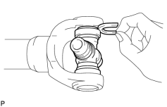
(g) Using a hammer, tap the yoke until there is no clearance between the bearing outer race and snap ring.
(h) Align the matchmarks on the propeller shaft and flange yoke or flange yoke and sleeve yoke.
(i) Install the flange yoke to the sleeve yoke or propeller shaft.
HINT:
Install 2 new spider bearings and snap rings on the flange yoke side using the procedure described above.
|
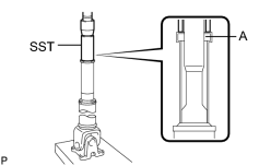
2. INSTALL PROPELLER SHAFT SLIDING SHAFT DUST COVER SUB-ASSEMBLY (a) Using SST and a press, press in a new dust cover. SST: 09636-20010 NOTICE: Place the universal joint straight when pressing in the dust cover. Apply MP grease to the 'A' part. |
|
3. INSTALL FRONT PROPELLER SHAFT UNIVERSAL JOINT SLEEVE YOKE SUB-ASSEMBLY
(a) Apply MP grease to the propeller shaft spline and sleeve yoke sliding surface.
(b) Align the matchmarks on the sleeve yoke and propeller shaft.
(c) Install the propeller shaft into the sleeve yoke.
|
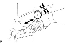
4. INSPECT SPIDER BEARING (a) Check that the spider bearing moves smoothly. (b) Check the spider bearing axial play. Maximum bearing axial play: 0 mm (0 in.) |
|
5. INSPECT PROPELLER SHAFT GREASE FITTING DIRECTION
HINT:
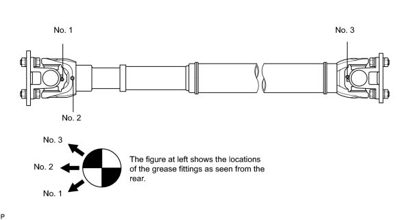
When replacing a spider bearing, be sure that the grease fitting hole is facing the direction shown in the illustration.

|

|