| Last Modified: 4-30-2014 | 6.6 A | Doc ID: RM0000018R8001X |
| Model Year: 2006 | Model: LX470 | Prod Date Range: [05/2005 - ] |
| Title: 2UZ-FE FUEL: FUEL INJECTOR: INSTALLATION; 2006 MY LX470 [05/2005 - ] | ||
INSTALLATION
1. INSTALL INJECTOR AND DELIVERY PIPE
NOTICE:
- Be careful not to drop the injectors when installing the delivery pipe.
- Since the O-ring may become stuck to the injector, do not apply a side load on it during the installation.
|
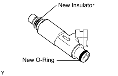
(a) Install a new insulator to each injector. |
|
(b) Apply a light coat of gasoline to a new O-ring and install it to each injector.
|
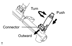
(c) While turning each injector clockwise and counterclockwise, push it into a delivery pipe. Install the 8 injectors. |
|
(d) Position each injector connector outward.
(e) Place the 4 spacers and 8 new insulators on the intake manifold.
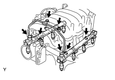
(f) Place the 2 delivery pipes and the injector assemblies on the lower intake manifold.
|
(g) Temporarily install the 4 nuts. |
|
(h) Install the front fuel pipe with the bolt, 4 new gaskets and 2 union bolts.
Torque:
39 N·m {400 kgf·cm, 29ft·lbf} for union bolt
7.5 N·m {77 kgf·cm, 66in·lbf} for bolt
|
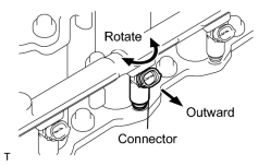
(i) Check that the injectors rotate smoothly. HINT: If the injectors do not rotate smoothly, the probable cause is incorrect installation of O-rings. Replace the O-rings in this case. |
|
(j) Position the injector connector outward.
(k) Tighten the 4 nuts holding the delivery pipes to the lower intake manifold.
Torque:
21 N·m {214 kgf·cm, 15ft·lbf}
(l) Connect the 8 injector connectors.
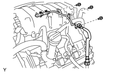
2. INSTALL FUEL RETURN PIPE
|
(a) Connect the hose to the fuel pressure regulator. |
|
(b) Install the pipe with the 3 bolts.
Torque:
7.5 N·m {77 kgf·cm, 13in·lbf}
|
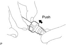
(c) Observe these precautions when connecting the fuel tube connector. |
|
(d) Check that there is no damage or contamination in the connected part of the pipe.
(e) Align the axis of the connector with the axis of the pipe. Push the pipe into the connector until the connector makes a "click" sound. If the connection is tight, apply a small amount of fresh engine oil on the tip of the pipe.
|
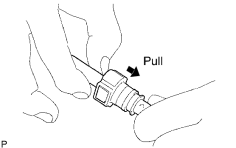
(f) After finishing the connection, try to pull apart the pipe and the connector to confirm that they are securely connected. |
|
|
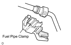
(g) Install the fuel pipe clamp to the connector. |
|
3. CONNECT ENGINE WIRE
|
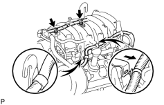
(a) Install the 2 wire clamps on the engine wire to the brackets on the delivery pipe RH. |
|
(b) Connect the engine wire clamps to the No. 1 engine hanger and engine wire bracket.
4. INSTALL PURGE VSV
(a) Install the purge VSV to the upper intake manifold with the bolt.
(b) Connect the purge line hose.
(c) Connect the purge VSV connector.
5. CONNECT VENTILATION HOSE
(a) Connect the ventilation hose to the ventilation valve.
6. INSTALL FUEL PRESSURE PULSATION DAMPER
|
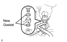
(a) Install 2 new gaskets and the fuel main hose with the fuel pressure pulsation damper. |
|
(b) Tighten the union bolt by hand.
|
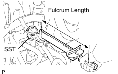
(c) Using SST, tighten the union bolt. SST: 09612-24014 Torque: 33 N·m {340 kgf·cm, 24ft·lbf} for use with SST 39 N·m {400 kgf·cm, 29ft·lbf} for use without SST HINT: Use a torque wrench with a fulcrum length of 30 cm (11.81 in.). |
|
7.
INSTALL INTAKE AIR CONNECTOR
![2006 MY LX470 [05/2005 - ]; 2UZ-FE ENGINE CONTROL SYSTEM: CAMSHAFT TIMING OIL CONTROL VALVE ASSEMBLY: INSTALLATION+](../../../../stylegraphics/info.gif "2006 MY LX470 [05/2005 - ]; 2UZ-FE ENGINE CONTROL SYSTEM: CAMSHAFT TIMING OIL CONTROL VALVE ASSEMBLY: INSTALLATION+")
8.
INSTALL V-BANK COVER
9. CONNECT CABLE TO NEGATIVE BATTERY TERMINAL
10. PERFORM INITIALIZATION
(a)
Perform initialization
.
NOTICE:
Certain systems need to be initialized after disconnecting and reconnecting the cable from the negative (-) battery terminal.

|

|