| Last Modified: 4-30-2014 | 6.6 J | Doc ID: RM0000018TH000X |
| Model Year: 2006 | Model: LX470 | Prod Date Range: [05/2005 - ] |
| Title: STEERING COLUMN: VARIABLE GEAR RATIO STEERING SYSTEM: TC and CG Terminal Circuit; 2006 MY LX470 [05/2005 - ] | ||
|
TC and CG Terminal Circuit |
DESCRIPTION
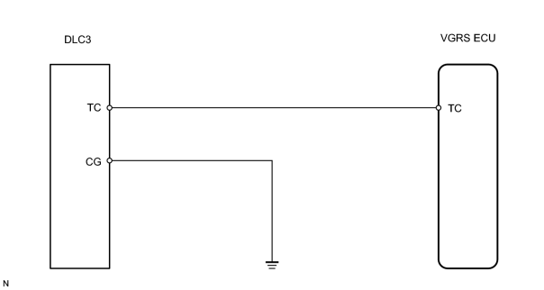
Connecting terminals TC and CG of the DLC3 causes the VGRS ECU to display the DTC by blinking the VGRS warning light.
WIRING DIAGRAM
INSPECTION PROCEDURE
PROCEDURE
|
1. |
CHECK VOLTAGE BETWEEN TERMINALS TC AND CG OF DLC3 |
|
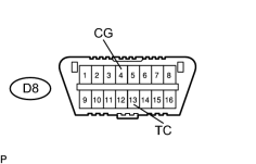
(a) Turn the ignition switch ON and measure the voltage between terminals D8-3 (TC) and D8-4 (CG) of the DLC3. Standard voltage: 10 to 14 V |
|
| OK |

|
IF VGRS WARNING LIGHT DOES NOT BLINK EVEN AFTER TC AND CG ARE CONNECTED, CHECK VGRS WARNING LIGHT CIRCUIT |
|

|
2. |
CHECK WIRE HARNESS (VGRS ECU - DLC3 AND BODY GROUND) |
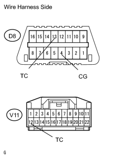
(a) Disconnect the V11 VGRS ECU connector.
|
(b) Measure the resistance according to the values in the table below. |
|
Standard resistance:
|
Tester Connection |
Specified Condition |
|---|---|
|
TC (V11-12) - TC (D8-13) |
Below 1 Ω |
|
TC (V11-12) - Body ground |
10 k Ω or higher |
|
CG (D8-4) - Body ground |
Below 1 Ω |
| NG |
|
| OK |
|

|

|