| Last Modified: 4-30-2014 | 6.6 J | Doc ID: RM0000018YX000X |
| Model Year: 2006 | Model: LX470 | Prod Date Range: [05/2005 - ] |
| Title: WIPER AND WASHER: WIPER AND WASHER SYSTEM: IG Power Source Circuit; 2006 MY LX470 [05/2005 - ] | ||
|
IG Power Source Circuit |
DESCRIPTION
This circuit is the power source for the wiper motor, the surrounding circuits, the CPU circuits and the input signal pull-up.
WIRING DIAGRAM
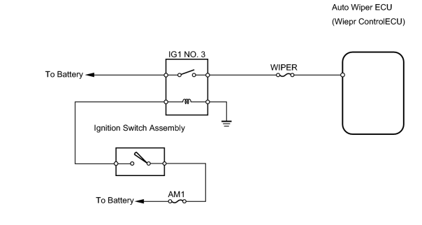
INSPECTION PROCEDURE
PROCEDURE
|
1. |
INSPECT FUSE (WIPER, AM1) |
(a) Remove the WIPER fuse from the cowl side junction block RH.
(b) Remove the AM1 fuse from the cowl side junction block LH.
(c) Measure the resistance of the fuses.
Standard resistance:
Below 1 Ω
| NG |

|
|

|
2. |
CHECK WIRE HARNESS (AUTO WIPER ECU (WIPER CONTROL ECU) - BODY GROUND) |
(a) Disconnect the A50 ECU connector.
(b) Measure the voltage of the wire harness side connector.
Standard voltage:
|
Tester Connection |
Condition |
Specified Condition |
|---|---|---|
|
A50-10 (WIG) - Body ground |
Ignition switch ON |
10 to 14 V |
|
A50-10 (WIG) - Body ground |
Ignition switch OFF |
Below 1 V |
| NG |
|
| OK |
|
PROCEED TO NEXT CIRCUIT INSPECTION SHOWN ON PROBLEM SYMPTOMS TABLE |

|

|