| Last Modified: 4-30-2014 | 6.6 A | Doc ID: RM0000018Z9001X |
| Model Year: 2006 | Model: LX470 | Prod Date Range: [05/2005 - ] |
| Title: A750F AUTOMATIC TRANSMISSION: FLOOR SHIFT ASSEMBLY: DISASSEMBLY; 2006 MY LX470 [05/2005 - ] | ||
DISASSEMBLY
1. REMOVE SHIFT LEVER KNOB SUB-ASSEMBLY
2. REMOVE POSITION INDICATOR HOUSING ASSEMBLY
(a) Using a small screwdriver, remove the shift lock release cover from the position indicator housing.
(b) Remove the position indicator housing assembly.
3. REMOVE POSITION INDICATOR LIGHT GUIDE
(a) Disconnect the indicator light wire from the position indicator light guide.
(b) Remove the position indicator light guide.
4. REMOVE SLIDE COVER AND NO. 2 SLIDE COVER
5. REMOVE SHIFT LEVER GUIDE HOUSING
(a) Disconnect the shift lock control ECU connector from the shift lever plate.
(b) Disconnect the 2 transmission control switches and the shift lock control switch from the shift lever guide housing.
|
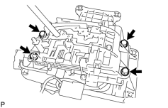
(c) Remove the 4 bolts, nuts and the shift lever guide housing. |
|
|
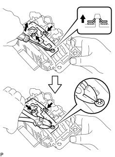
6. DISASSEMBLE SHIFT LEVER GUIDE HOUSING (a) Using a screwdriver, pry up the 3 shift lever nuts. (b) Using nippers, cut the 3 shift lever nuts off. HINT: Remove the shift lever lock pin of the shift lever nut in the same way. (c) Remove the shift lever guide cushion. (d) Remove the 3 screws shift lock control ECU and shift lock solenoid. (e) Remove the shift lock control ECU bracket from the shift lock control ECU. (f) Disconnect the transmission control switch connector from the shift lever guide housing. (g) Remove the shift lock release button and spring. (h) Using a screwdriver, pry up the shift lever nut. (i) Using a nipper, cut the shift lever nut off. (j) Remove the shift lever lock pin, the shift lock plate stopper and the cushion. |
|
7. DISCONNECT SHIFT LOCK CONTROL ECU, SHIFT LOCK SOLENOID, SHIFT LOCK CONTROL SWITCH AND TRANSMISSION CONTROL SWITCH
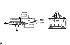
(a) Disengage the secondary locking device of the shift lock solenoid.
(b) Release the locking lug of the terminal 4 and 5, and pull the terminals out from the rear.
HINT:
Remove the transmission control switch in the same way.
(c) Remove the shift lock solenoid.
|
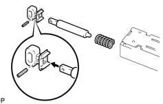
(d) Using 2 mm diameter. steel wire, remove the pin and the shift lock solenoid link from the shift lock solenoid plunger. |
|
(e) Disengage the secondary locking device of the shift lock control ECU.
(f) Release the locking lag of the terminal 1, 2 and 8 pull the terminals out from the rear.
(g) Remove the transmission control switch (D - 4 position).
(h) Release the locking lag of the terminal 5, 6 and 12 and pull the terminals out from the rear.
(i) Remove the transmission control switch (2 - L position).
(j) Release the locking lag of the terminal 7 and 14 and pull the terminals out from the rear.
8. DISCONNECT INDICATOR LIGHT WIRE
9. REMOVE FLOOR SHIFT LEVER SUB-ASSEMBLY
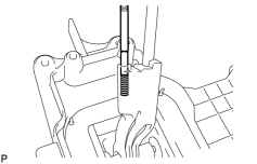
(a) Using a magnetic finger, remove the detent shift lever pin and spring.
|
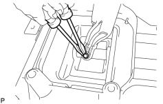
(b) Using 2 screwdrivers, remove the shift lever ring. |
|
(c) Remove the pin and shift lever.
10. DISASSEMBLE SHIFT LEVER PLATE SUB-ASSEMBLY
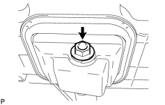
(a) Remove the nut, control lever, plate washer, 2 spacers and 2 O-rings.
|
(b) Using pliers, remove the clip. |
|
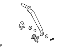
(c) Remove the swivel, 2 plate washers, shaft lower control bush and spacer.
(d) Remove the shift lever seal.
(e) Remove the 4 collars.
(f) Remove the 2 spring nuts.

|

|