| Last Modified: 4-30-2014 | 6.6 G | Doc ID: RM000001909000X |
| Model Year: 2006 | Model: LX470 | Prod Date Range: [05/2005 - ] |
| Title: MIRROR: POWER MIRROR CONTROL SYSTEM: INSPECTION; 2006 MY LX470 [05/2005 - ] | ||
INSPECTION
1. INSPECT OUTER REAR VIEW MIRROR SWITCH ASSEMBLY
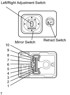
(a) The L side of the left/right adjustment switch:
Check the continuity of the mirror switch.
OK:
|
Tester Connection |
Switch Condition |
Specified Condition |
|---|---|---|
|
3 - 4 1 - 7 7 - 8 |
UP |
Continuity |
|
OFF |
No continuity |
|
|
1 - 3 3 - 8 4 - 7 |
DOWN |
Continuity |
|
OFF |
No continuity |
|
|
4 - 9 1 - 7 7 - 8 |
LEFT |
Continuity |
|
OFF |
No continuity |
|
|
4 - 7 1 - 8 8 - 9 |
RIGHT |
Continuity |
|
OFF |
No continuity |
If the continuity is not as specified, replace the switch.
(b) The R side of the left/right adjustment switch:
Check the continuity of the mirror switch.
OK:
|
Tester Connection |
Switch Condition |
Specified Condition |
|---|---|---|
|
2 - 4 1 - 7 7 - 8 |
UP |
Continuity |
|
OFF |
No continuity |
|
|
4 - 7 1 - 2 2 - 8 |
DOWN |
Continuity |
|
OFF |
No continuity |
|
|
4 - 10 1 - 7 7 - 8 |
LEFT |
Continuity |
|
OFF |
No continuity |
|
|
4 - 7 1 - 8 8 - 10 |
RIGHT |
Continuity |
|
OFF |
No continuity |
If the continuity is not as specified, replace the switch.
|
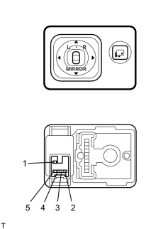
(c) Check the continuity of the retract switch. OK:
If the continuity is not as specified, replace the switch. |
|
|
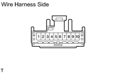
(d) Check the mirror switch circuit. (1) Disconnect the connector from the switch and check the connector on the wire harness side. OK:
If the circuit is not as specified, inspect the parts connected to the circuit. |
|
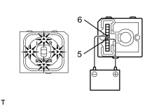
(e) Check the indicator light operation.
|
(1) Connect the positive (+) lead from the battery to terminal 5 and the negative (-) lead to terminal 6, and check that the indicator light lights up. If the indicator light does not light up, replace the switch. |
|
2. INSPECT OUTER REAR VIEW MIRROR ASSEMBLY
(a) Check the mirror motor operation.
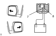
(1) Connect the positive (+) lead from the battery to terminal 8 and the negative (-) lead to terminal 7, and check that the mirror surface turns outward.
|
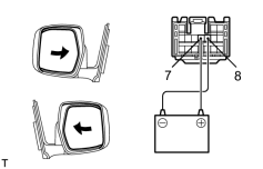
(2) Reverse the polarity of the battery leads, and check that the mirror surface turns inward. |
|
|
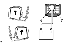
(3) Connect the battery positive (+) lead to terminal 6 and the battery negative (-) lead to terminal 7, and check that the mirror turns upward. |
|
|
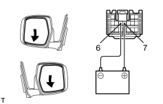
(4) Reverse the polarity of the battery leads, and check that the mirror turns downward. If the operation is not as specified, replace the mirror assembly. |
|
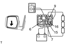
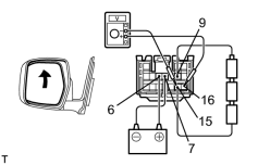
(b) w/ Driving position memory:
Check the mirror position sensor operation.
HINT:
Strip off the vinyl tape on the connector and remove terminals 6, 7, 9, 10, 15 and 16 from the connector housing.
(1) Connect 3 1.5 V dry cell batteries in series.
(2) Connect the positive (+) lead from the dry cell batteries to terminal 9 and its negative (-) lead to terminal 15.
|
(3) Connect the voltmeter positive (+) lead to terminal 16 and the voltmeter negative (-) lead to terminal 15. |
|
(4) Apply battery positive voltage to terminal 7 and 6, and then check that the voltage gradually changes as shown in the table below while the mirror moves between the uppermost position and the lowermost position.
Standard voltage:
|
Mirror Position |
Lowermost |
Mirror Position |
Uppermost |
|---|---|---|---|
|
Voltage |
2.8 to 5.0 |
Changes Gradually |
0 to 1.8 |
If the voltage value is not as specified, replace the mirror assembly.
(5) Disconnect the 4 leads of the battery and voltmeter.
|
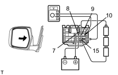
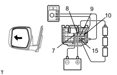
(6) Connect the voltmeter positive (+) lead to terminal 10 and the voltmeter negative (-) lead to terminal 15. |
|
|
(7) Apply battery positive voltage to terminal 7 and 8, and then check that the voltage gradually changes as shown in the table below while the mirror moves between the leftmost position and rightmost position. Standard voltage:
If the voltage value is not as specified, replace the mirror assembly. |
|
|
3. INSPECT DRIVING POSITION MEMORY AND RETURN SWITCH (a) Check the continuity of the switch. OK:
If the continuity is not as specified, replace the switch. |
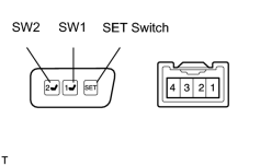
|
4. INSPECT MIRROR CONTROL ECU CIRCUIT
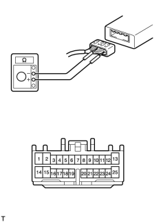
(a) Disconnect the connector from the ECU and inspect the connector on the wire harness side.
OK:
|
Tester Connection |
Condition |
Specified Condition |
|---|---|---|
|
3 - 16 |
Right side mirror switch to RIGHT |
Continuity |
|
4 - 16 |
Left side mirror switch to RIGHT |
Continuity |
|
5 - 16 |
Right side mirror switch to DOWN |
Continuity |
|
6 - 16 |
Left side mirror switch to DOWN |
Continuity |
|
3 - 17 |
Right side mirror switch to LEFT |
Continuity |
|
4 - 17 |
Left side mirror switch to LEFT |
Continuity |
|
5 - 17 |
Right side mirror switch to UP |
Continuity |
|
6 - 17 |
Left side mirror switch to UP |
Continuity |
|
7 - 19 |
Constant |
Continuity |
|
14 - Ground |
Constant |
Continuity |
If the circuit is not as specified, inspect the circuits connected to other parts.
|
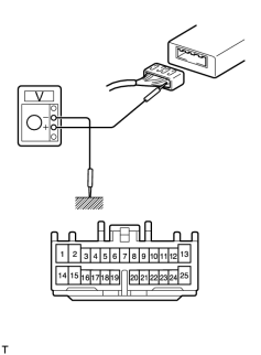
(b) Disconnect the connector from the ECU and inspect the connector on the wire harness side. OK:
If the circuit is not as specified, inspect the circuits connected to other parts. |
|
|
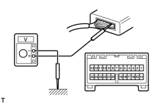
5. INSPECT MIRROR CONTROL ECU OPERATION (a) Connect the connectors, and using a voltmeter with high impedance (10 kΩ/V minimum), measure the voltage at each terminal and body ground. OK:
*: Confirm that the voltage changes gradually while the mirror moves. If the operation is not as specified, inspect the wire harness, the mirror switch or the mirror assembly. If these are correct, replace the ECU. |
|

|

|