- "TRANSLATE ECU" is not displayed on "BUS CHECK" of intelligent tester
- Applies to "TRANSLATE ECU COMMUNICATION STOP MODE" in "DTC COMBINATION TABLE"
| Last Modified: 4-30-2014 | 6.6 J | Doc ID: RM0000019YE001X |
| Model Year: 2006 | Model: LX470 | Prod Date Range: [05/2005 - ] |
| Title: CAN COMMUNICATION: CAN COMMUNICATION SYSTEM: Translate ECU Communication Stop Mode; 2006 MY LX470 [05/2005 - ] | ||
|
Translate ECU Communication Stop Mode |
DESCRIPTION
|
Detection Item |
Symptom |
Trouble Area |
|---|---|---|
|
Translate ECU communication stop mode |
|
|
WIRING DIAGRAM
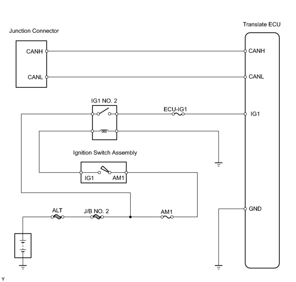
INSPECTION PROCEDURE
PROCEDURE
|
1. |
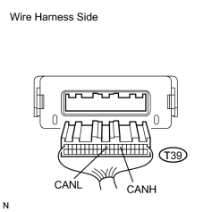
CHECK CAN BUS LINE FOR DISCONNECTION (TRANSLATE ECU SUB BUS LINE) |
|
(a) Disconnect the T39 translate ECU connector. (b) Measure the resistance of the wire harness side connector. Standard resistance:
|
|
| NG |

|
REPAIR OR REPLACE TRANSLATE ECU SUB BUS LINE OR CONNECTOR (CAN-H, CAN-L) |
|

|
2. |
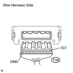
CHECK WIRE HARNESS (TRANSLATE ECU - BATTERY AND BODY GROUND) |
|
(a) Disconnect the T39 translate ECU connector. (b) Measure the resistance of the wire harness side connector. Standard resistance:
(c) Measure the voltage of the wire harness side connector. Standard voltage:
|
|
| NG |
|
| OK |
|

|

|