| Last Modified: 4-30-2014 | 6.6 U | Doc ID: RM0000019YQ000X |
| Model Year: 2006 | Model: LX470 | Prod Date Range: [05/2005 - ] |
| Title: PARK ASSIST / MONITORING: NIGHT VIEW SYSTEM: TERMINALS OF ECU; 2006 MY LX470 [05/2005 - ] | ||
TERMINALS OF ECU
1. CHECK NIGHT VIEW ECU
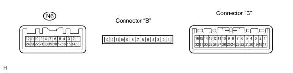
|
Symbols (Terminal No.) |
Wiring Color |
Terminal Description |
Condition |
Specified Condition |
|---|---|---|---|---|
|
+B (N6-1) - Body ground |
G-R - Body ground |
Battery |
Always |
10 to 14 V |
|
IG (N6-2) - Body ground |
R-L - Body ground |
Ignition switch |
Ignition switch OFF |
0 V |
|
Ignition switch ON |
10 to 14 V |
|||
|
CNTSV (N6-3) - Body ground |
LG - Body ground |
Power source of night view switch |
When night view system starts up |
4.75 to 5.25 V |
|
REO (N6-4) - Body ground |
LG-B - Body ground |
Rheostat signal of night view switch |
When night view system starts up |
Max. 0 V to Min. 5 V |
|
NVSW (N6-5) - Body ground |
G-W - Body ground |
Night view switch signal |
Ignition switch ON and night view switch FREE |
5 V |
|
Ignition switch ON and night view switch PUSH |
0 V |
|||
|
4P (N6-6) - Body ground |
V - Body ground |
Speed signal from combination meter |
Ignition switch ON and turn rear wheel slowly |
Pulse generation |
|
LAMP (N6-7) - Body ground |
G-W - Body ground |
Night view projector relay signal |
Ignition switch ON and night view main indicator comes on |
10 to 14 V |
|
IND1 (N6-9) - Body ground |
G-Y - Body ground |
Main indicator illumination signal of night view switch |
Ignition switch ON and night view main indicator comes on |
4.5 to 10 V |
|
IND2 (N6-10) - Body ground |
G-B - Body ground |
Beam indicator illumination signal of night view switch |
When night view system starts up |
4.5 to 10 V |
|
HF (N6-11) - Body ground |
R-B - Body ground |
Headlight dimmer switch signal |
Headlight dimmer switch FLASH position |
Below 2 V |
|
HU (N6-12) - Body ground |
R-Y - Body ground |
Headlight dimmer switch signal |
Headlight dimmer switch ON position |
Below 2 V |
|
HERLY (N6-13) - Body ground |
R-W - Body ground |
Headlight relay signal |
Headlight dimmer switch in LO or HI position and light control switch in HEAD position |
Below 2 V |
|
CON (N6-14) - Body ground |
Y - Body ground |
Automatic light control sensor signal |
Ignition switch ON |
Pulse generation (10 to 14 V) |
|
NTSC (N6-15) - Body ground |
R - Body ground |
NTSC signal from camera |
Night view system start up and night view display is displayed |
Pulse generation |
|
NTSCRE (N6-16) - Body ground |
Shielded - Body ground |
Ground |
Always |
Below 1 V |
|
6VOUT(N6-17) - Body ground |
B - Body ground |
Power source of camera |
When night view system starts up |
5.7 to 6.3 V |
|
6VRET (N6-18) - Body ground |
W - Body ground |
Ground |
Always |
Below 1 V |
|
GND (N6-20) - Body ground |
W-B - Body ground |
Ground |
Always |
Below 1 V |
|
GND (N6-21) - Body ground |
W-B - Body ground |
Ground |
Always |
Below 1 V |
|
+B (B-1) - Body ground |
R - Body ground |
Battery |
Always |
10 to 14 V |
|
IG (B-2) - Body ground |
R - Body ground |
Ignition switch |
Ignition switch OFF |
0 V |
|
Ignition switch ON |
10 to 14 V |
|||
|
GND (B-4) - Body ground |
B - Body ground |
Ground |
Always |
Below 1 V |
|
GND (B-5) - Body ground |
B - Body ground |
Ground |
Always |
Below 1 V |
|
6VIN (B-6) - Body ground |
V - Body ground |
Power source of camera (input) |
Ignition switch ON |
5.7 to 6.3 V |
|
5V (B-7) - Body ground |
W - Body ground |
Power source of night view switch (input) |
Ignition switch ON |
4.75 to 5.25 V |
|
VGH (B-8) - Body ground |
G - Body ground |
Power source of display (input) |
Ignition switch ON |
17.4 to 18.6 V |
|
VDD2 (B-9) - Body ground |
L - Body ground |
Power source of display (input) |
Ignition switch ON |
7.2 to 8.0 V |
|
VDD (B-10) - Body ground |
O - Body ground |
Power source of display (input) |
Ignition switch ON |
4.75 to 5.25 V |
|
VEE2 (B-11) - Body ground |
Y - Body ground |
Power source of display (input) |
Ignition switch ON |
-4.7 to -5.3 V |
|
VGL (B-12) - Body ground |
BR - Body ground |
Power source of display (input) |
Ignition switch ON |
-15 to -17 V |
|
GND (B-13) - Body ground |
B - Body ground |
Ground |
Always |
Below 1 V |
|
HSY (C-1) - Body ground |
V - Body ground |
Display control signal |
Ignition switch ON |
Pulse generation (5 V) |
|
POLS (C-2) - Body ground |
BR - Body ground |
Display control signal |
Ignition switch ON |
Pulse generation (5 V) |
|
CSYNC (C-3) - Body ground |
W - Body ground |
Display signal (Synchronize) |
Ignition switch ON |
Pulse generation (6 V) |
|
COM (C-4) - Body ground |
G - Body ground |
Display control signal |
Ignition switch ON |
Pulse generation (7 V) |
|
VB (C-6) - Body ground |
L - Body ground |
Display signal (Bus) |
Ignition switch ON |
Pulse generation (5 V) |
|
VR (C-7) - Body ground |
GR - Body ground |
Display signal (Red) |
Ignition switch ON |
Pulse generation (5 V) |
|
VG (C-8) - Body ground |
O - Body ground |
Display signal (Green) |
Ignition switch ON |
Pulse generation (5 V) |
|
GND (C-9) - Body ground |
B - Body ground |
Ground |
Always |
Below 1 V |
|
MS1 (C-10) - Body ground |
Y - Body ground |
Display cover position signal |
Ignition switch ON and display cover of night view display CLOSED |
0 V |
|
Ignition switch ON and display cover of night view display OPEN |
5 V |
|||
|
MS2 (C-11) - Body ground |
V - Body ground |
Display cover position signal |
Ignition switch ON and display cover of night view display CLOSED |
0 V |
|
Ignition switch ON and display cover of night view display OPEN |
5 V |
|||
|
MD1 (C-12) - Body ground |
BR - Body ground |
Power source of cover motor |
Ignition switch ON and display cover of night view display CLOSED |
0 V |
|
Ignition switch ON and display cover of night view display OPEN |
10 V |
|||
|
MD2 (C-13) - Body ground |
W - Body ground |
Power source of cover motor |
Ignition switch ON and display cover of night view display CLOSED |
0 V |
|
Ignition switch ON and display cover of night view display OPEN |
10 V |
|||
|
VGL (C-15) - Body ground |
G - Body ground |
Power source of display |
Ignition switch ON |
-15 to -17 V |
|
VDD (C-17) - Body ground |
L - Body ground |
Power source of display |
Ignition switch ON |
4.75 to 5.25 V |
|
VGH (C-19) - Body ground |
GR - Body ground |
Power source of display |
Ignition switch ON |
17.4 to 18.6 V |
|
GND (C-22) - Body ground |
B - Body ground |
Ground |
Always |
Below 1 V |
|
GND (C-23) - Body ground |
B - Body ground |
Ground |
Always |
Below 1 V |
|
DIM (C-24) - Body ground |
O - Body ground |
Display back light control signal |
Vehicle stop |
Pulse generation (Duty 10 %) |
|
Vehicle running (approximately 6 km/h) |
Pulse generation (Duty 90 %) |
|||
|
C/C CUT (C-25) - Body ground |
Y - Body ground |
Display back light control signal |
When night view system starts up |
5 V |
|
C/C FH (C-26) - Body ground |
V - Body ground |
Display back light control signal |
When night view system starts up |
Pulse generation (5 V) |
|
IG (C-28) - Body ground |
R - Body ground |
Ignition switch |
Ignition switch OFF |
0 V |
|
Ignition switch ON |
10 to 14 V |
2. CHECK NIGHT VIEW DISPLAY
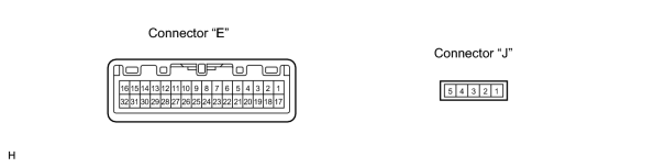
|
Symbols (Terminal No.) |
Wiring Color |
Terminal Description |
Condition |
Specified Condition |
|---|---|---|---|---|
|
HYS (E-1) - Body ground |
V - Body ground |
Display control signal |
Ignition switch ON |
Pulse generation (5 V) |
|
POLS (E-2) - Body ground |
BR - Body ground |
Display control signal |
Ignition switch ON |
Pulse generation (5 V) |
|
CSYNC (E-3) - Body ground |
W - Body ground |
Display signal (Synchronize) |
Ignition switch ON |
Pulse generation (5 V) |
|
COM (E-4) - Body ground |
G - Body ground |
Display control signal |
Ignition switch ON |
Pulse generation (5 V) |
|
VB (E-6) - Body ground |
L - Body ground |
Display signal (Blue) |
Ignition switch ON |
Pulse generation (5 V) |
|
VR (E-7) - Body ground |
GR - Body ground |
Display signal (Red) |
Ignition switch ON |
Pulse generation (5 V) |
|
VG (E-8) - Body ground |
O - Body ground |
Display signal (Green) |
Ignition switch ON |
Pulse generation (5 V) |
|
GND (E-9) - Body ground |
B - Body ground |
Ground |
Always |
Below 1 V |
|
MS1 (E-10) - Body ground |
Y - Body ground |
Display cover position signal (output) |
Ignition switch ON and display cover of night view display CLOSED |
0 V |
|
Ignition switch ON and display cover of night view display OPEN |
5 V |
|||
|
MS2 (E-11) - Body ground |
V - Body ground |
Display cover position signal (output) |
Ignition switch ON and display cover of night view display CLOSED |
0 V |
|
Ignition switch ON and display cover of night view display OPEN |
5 V |
|||
|
MD1 (E-12) - Body ground |
BR - Body ground |
Power source of cover motor (input) |
Ignition switch ON and display cover of night view display CLOSED |
0 V |
|
Ignition switch ON and display cover of night view display OPEN |
10 V |
|||
|
MD2 (E-13) - Body ground |
W - Body ground |
Power source of cover motor (input) |
Ignition switch ON and display cover of night view display CLOSED |
0 V |
|
Ignition switch ON and display cover of night view display OPEN |
10 V |
|||
|
VGL (E-15) - Body ground |
G - Body ground |
Power source of display |
Ignition switch ON |
-1.5 to -17 V |
|
VDD (E-17) - Body ground |
L - Body ground |
Power source of display |
Ignition switch ON |
4.75 to 5.25 V |
|
VGH (E-19) - Body ground |
GR - Body ground |
Power source of display |
Ignition switch ON |
17.4 to 18.6 V |
|
GND (E-223) - Body ground |
B - Body ground |
Ground |
Always |
Below 1 V |
|
GND (E-23) - Body ground |
B - Body ground |
Ground |
Always |
Below 1 V |
|
DIM (E-24) - Body ground |
O - Body ground |
Display back light control signal |
Vehicle stop |
Pulse generation (Duty 10 %) |
|
Vehicle running (approximately 6 km/h) |
Pulse generation (Duty 90 %) |
|||
|
C/C CUT (E-25) - Body ground |
Y - Body ground |
Display back light control signal |
When night view system starts up |
5 V |
|
C/C FH (E-26) - Body ground |
V - Body ground |
Display back light control signal |
When night view system starts up |
Pulse generation (5 V) |
|
IG (E-28) - Body ground |
R - Body ground |
Ignition switch |
Ignition switch OFF |
0 V |
|
Ignition switch ON |
10 to 14 V |
|||
|
MS1 (J-1) - Body ground |
L - Body ground |
Display cover position signal (input) |
Ignition switch ON and display cover of night view display CLOSED |
0 V |
|
Ignition switch ON and display cover of night view display OPEN |
5 V |
|||
|
MS2 (J-2) - Body ground |
W - Body ground |
Display cover position signal (input) |
Ignition switch ON and display cover of night view display CLOSED |
0 V |
|
Ignition switch ON and display cover of night view display OPEN |
5 V |
|||
|
MSCOM (J-3) - Body ground |
Y - Body ground |
Display light control signal |
Always |
Below 1 V |
|
MD1 (J-4) - Body ground |
R - Body ground |
Power source of cover motor (output) |
Ignition switch ON and display cover of night view display CLOSED |
0 V |
|
Ignition switch ON and display cover of night view display OPEN |
10 V |
|||
|
MD2 (J-5) - Body ground |
B - Body ground |
Power source of cover motor (output) |
Ignition switch ON and display cover of night view display CLOSED |
0 V |
|
Ignition switch ON and display cover of night view display OPEN |
10 V |
3. CHECK NIGHT VIEW BATTERY ECU

|
Symbols (Terminal No.) |
Wiring Color |
Terminal Description |
Condition |
Specified Condition |
|---|---|---|---|---|
|
+B (D-1) - Body ground |
R - Body ground |
Battery |
Always |
10 to 14 V |
|
IG (D-2) - Body ground |
R - Body ground |
Ignition switch |
Ignition switch OFF |
0 V |
|
Ignition switch ON |
10 to 14 V |
|||
|
GND (D-4) - Body ground |
B - Body ground |
Ground |
Always |
Below 1 V |
|
GND (D-5) - Body ground |
B - Body ground |
Ground |
Always |
Below 1 V |
|
6VOUT (D-7) - Body ground |
V - Body ground |
Power source of camera |
Ignition switch ON |
5.7 to 6.3 V |
|
5V (D-8) - Body ground |
W - Body ground |
Power source of night view switch |
Ignition switch ON |
4.75 to 5.25 V |
|
VGH (D-10) - Body ground |
G - Body ground |
Power source of display |
Ignition switch ON |
17.4 to 18.6 V |
|
VDD2 (D-11) - Body ground |
L - Body ground |
Power source of display |
Ignition switch ON |
7.2 to 8.0 V |
|
VDD (D-12) - Body ground |
O - Body ground |
Power source of display |
Ignition switch ON |
4.75 to 5.25 V |
|
VEE2 (D-13) - Body ground |
Y - Body ground |
Power source of display |
Ignition switch ON |
-4.7 to -5.3 V |
|
VGL (D-14) - Body ground |
BR - Body ground |
Power source of display |
Ignition switch ON |
-15 to -17 V |
|
GND (D-16) - Body ground |
B - Body ground |
Ground |
Always |
Below 1 V |

|

|