| Last Modified: 4-30-2014 | 6.6 A | Doc ID: RM0000019ZF001X |
| Model Year: 2006 | Model: LX470 | Prod Date Range: [05/2005 - ] |
| Title: BRAKE: HYDRAULIC BRAKE BOOSTER: REASSEMBLY; 2006 MY LX470 [05/2005 - ] | ||
REASSEMBLY
|
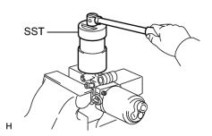
1. INSTALL BRAKE BOOSTER ACCUMULATOR ASSEMBLY (a) Install the silencer, spring and a new O-ring. (b) Using SST, install the accumulator. SST: 09318-12010 Torque: 54 N·m {550 kgf·cm, 36ft·lbf} |
|
2. INSTALL PISTON
NOTICE:
- If the piston is installed at an angle, there is possibility that the cylinder bore could be damaged.
- Be careful not to damage the rubber lips on the pistons.
|
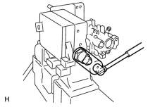
3. INSTALL OIL PRESSURE SENSOR (a) Using a 30 mm deep socket, install the oil pressure sensor. Torque: 81 N·m {830 kgf·cm, 60ft·lbf} NOTICE: If replacing the pressure sensor, since the sensor is non-reusable, use a sensor of the supply part No. shown below. Part No.: 89637-30050 |
|
4. INSTALL BRAKE BOOSTER PUMP ASSEMBLY
(a) Install the cushion to the No. 2 pump bracket.
(b) Install the No. 2 pump bracket with the 2 bolts.
(c) Install the 2 washers, 2 cushions, 2 collars and sleeve.
(d) Install the No. 1 pump bracket with the bolt.
(e) Install the booster pump with the 2 bolts.
|
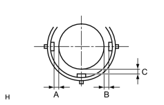
(f) Install the accumulator bracket with the 2 bolts. (1) When installing the accumulator bracket, adjust to secure the clearance as shown in the illustration. A + B: 0.1 mm (0.161 in.) or less C: 0.3 to 3.8 mm (0.012 to 0.150 in.) HINT: Secure more than 0.3 mm (0.012 in.) clearance for A and B each. |
|
(g) Install the wire harness to the booster pump with the 4 screws.
(h) Install the actuator hose.
|
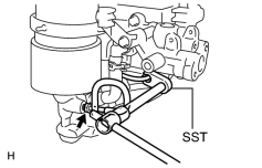
5. INSTALL NO. 1 BRAKE ACTUATOR TUBE (a) Using SST, install the actuator tube. SST: 09023-00101 Torque: 15 N·m {155 kgf·cm, 11ft·lbf} without SST 14 N·m {143 kgf·cm, 10ft·lbf} with SST HINT: Use a torque wrench with a fulcrum length of 30 cm (11.81 in.). |
|
6. INSTALL CYLINDER BOOT
(a) Install the cylinder boot.
7. INSTALL MASTER CYLINDER PUSH ROD CLEVIS
(a) Install the clevis and lock nut.
(b) Tighten the lock nut.
Torque:
25 N·m {260 kgf·cm, 19ft·lbf}
8. INSTALL BRAKE MASTER CYLINDER RESERVOIR SUB-ASSEMBLY
(a) Install the 3 grommets.
(b) Install the reservoir with the 3 screws.
Torque:
1.7 N·m {17.5 kgf·cm, 15.2in·lbf}
(c) Install the reservoir cap.
9. INSTALL FLUID LEVEL WARNING SWITCH CONNECTOR CLAMP
(a) Install the clamp with the bolt.
(b) Connect the connector.

|

|