- ECU terminal IG1 voltage is 9.5 V to 17.0 V and the solenoid relay is ON; however, the contact point of the solenoid relay is OFF.
- With solenoid relay ON, ECU terminal IG1 voltage becomes 9.5 V or less and the contact point of the solenoid relay does not become ON.
| Last Modified: 4-30-2014 | 6.6 C | Doc ID: RM000001A5M002X |
| Model Year: 2006 | Model: LX470 | Prod Date Range: [05/2005 - ] |
| Title: BRAKE CONTROL: VEHICLE STABILITY CONTROL SYSTEM: C0278/11,C0279/12; Open or Short Circuit in ABS Solenoid Relay Circuit; 2006 MY LX470 [05/2005 - ] | ||
|
DTC |
C0278/11 |
Open or Short Circuit in ABS Solenoid Relay Circuit |
|
DTC |
C0279/12 |
Short to B+ in ABS Solenoid Relay Circuit |
DESCRIPTION
This relay supplies power to each ABS solenoid. After the ignition switch is turned ON, if the initial check is OK, the relay turns on.
|
DTC No. |
DTC Detection Condition |
Trouble Area |
|---|---|---|
|
C0278/11 |
Conditions 1. and 2. continue for 0.2 sec. or more: |
|
|
C0279/12 |
Immediately after ECU terminal IG1 becomes ON, and solenoid relay is OFF; however, when the condition that the solenoid relay due to the contact point is ON continues for 0.2 sec. or more. |
WIRING DIAGRAM
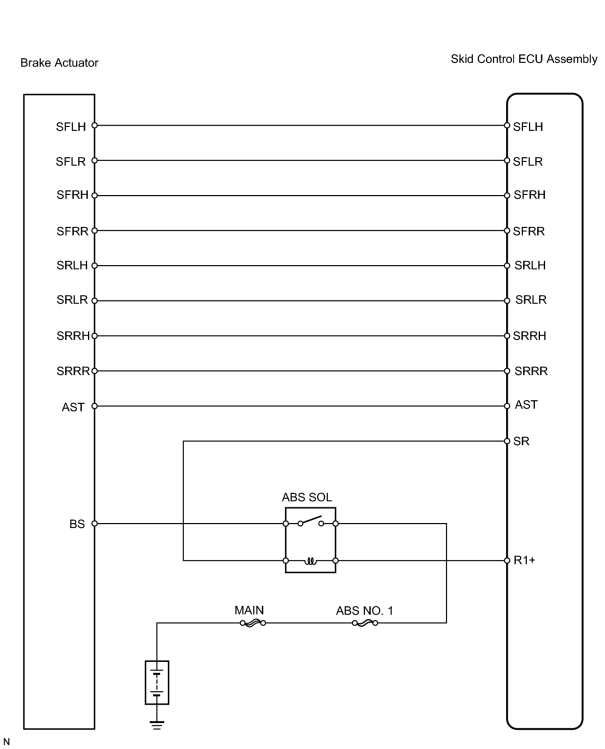
INSPECTION PROCEDURE
HINT:
When using the intelligent tester, start from *1. When not using the intelligent tester, start from *2.
PROCEDURE
|
1. |
PERFORM ACTIVE TEST (ABS SOLENOID RELAY)*1 |
(a) Select the ACTIVE TEST, generate a control command, and then check that the ABS solenoid relay operates.
Skid control ECU assembly
|
Item |
Vehicle Condition / Test Details |
Diagnostic Note |
|---|---|---|
|
SOL RELAY |
Turns ABS solenoid relay ON / OFF |
Operation of solenoid (clicking sound) can be head |
OK:
Operation sound of the ABS solenoid relay should be heard.
| OK |

|
|

|
2. |
CHECK WIRE HARNESS (BRAKE ACTUATOR - ENGINE ROOM RELAY BLOCK)*2 |
|
(a) Remove the ABS SOL relay from the engine room relay block. (b) Disconnect the A43 actuator connector. (c) Measure the resistance of the wire harness side connectors. Standard resistance:
|
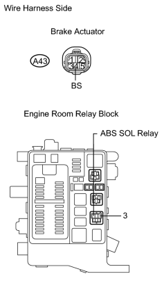
|
| NG |
|
|
|
3. |
INSPECT RELAY (Marking: ABS SOL) |
|
(a) Remove the ABS SOL relay from the engine room relay block. (b) Measure the resistance of the relay. Standard resistance:
|
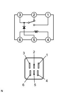
|
| NG |
|
|
|
4. |
INSPECT BRAKE ACTUATOR |
|
(a) Disconnect the A43 and A44 actuator connectors. (b) Measure the resistance of the actuator. Standard resistance:
|
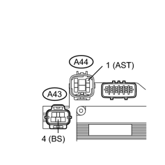
|
| NG |
|
|
|
5. |
CHECK WIRE HARNESS (SKID CONTROL ECU ASSEMBLY - ABS SOLENOID RELAY) |
| NG |
|
| OK |
|
CHECK EACH CONNECTION IF SAME CODE IS STILL OUTPUT AFTER DTC DELETION (IF CONNECTOR IS NORMAL, SKID CONTROL ECU MAY BE DEFECTIVE) |
|
6. |
CHECK WIRE HARNESS (SKID CONTROL ECU ASSEMBLY - BRAKE ACTUATOR) |
(a) Check for open circuit in harness and connectors.
| NG |
|
|
|
7. |
CHECK OPERATION OF BRAKE ACTUATOR WITH NEW OR NORMALLY FUNCTIONING BRAKE ACTUATOR |
(a) Temporarily replace the brake actuator with a new or normally functioning one.
(b) Check that the malfunction disappears.
OK:
Malfunction disappears.
| NG |
|
| OK |
|

|

|