![2006 MY LX470 [05/2005 - ]; BRAKE CONTROL: VEHICLE STABILITY CONTROL SYSTEM: ABS Warning Light Circuit](../../../../stylegraphics/info.gif "2006 MY LX470 [05/2005 - ]; BRAKE CONTROL: VEHICLE STABILITY CONTROL SYSTEM: ABS Warning Light Circuit")
- Right front speed sensor
- Sensor installation
- Sensor rotor
| Last Modified: 4-30-2014 | 6.6 D | Doc ID: RM000001A5P002X |
| Model Year: 2006 | Model: LX470 | Prod Date Range: [05/2005 - ] |
| Title: BRAKE CONTROL: VEHICLE STABILITY CONTROL SYSTEM: OPERATION CHECK; 2006 MY LX470 [05/2005 - ] | ||
OPERATION CHECK
|
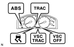
1. CHECK WARNING LIGHT AND INDICATOR LIGHT (a) Release the parking brake lever. NOTICE: When releasing the parking brake lever, move the shift lever into the P position to hold the vehicle for safety. (b) When the ignition switch is turned ON, check that the ABS, VSC TRAC and BRAKE warning lights, VSC OFF, SLIP and TRAC indicator lights come on for 3 seconds. (c) When depressing the brake pedal repeatedly, it may turn on the ABS, VSC TRAC and BRAKE warning light, VSC OFF indicator light and VSC buzzer. HINT:
|
|
2. CHECK SENSOR SIGNAL BY TEST MODE (When not using intelligent tester)
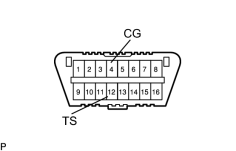
(a) Procedures for test mode:
(1) Turn the ignition switch OFF.
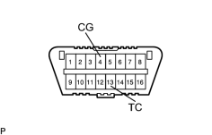
(2) Using SST, connect terminals 12 (TS) and 4 (CG) of DLC3.
SST: 09843-18040
(3) Check that the steering wheel is in the straight-ahead position and move the shift lever to P.
(4) Turn the ignition switch ON.
|
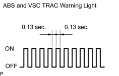
(5) Check that the ABS warning light and VSC TRAC warning light blinks as shown in illustration. HINT: If no code appears, check the TC circuit, ABS warning light circuit and VSC TRAC warning light circuit.
|
|
(b) Check the deceleration sensor.
(1) Create gravitational force (0.2 G or more) on the vehicle through deceleration. Use one of the following methods to decelerate the vehicle in the direction it is moving:
- Apply the brakes.
- Drive over a bump.
- Drive on an incline.
|
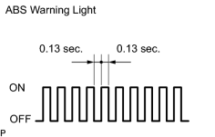
(2) When the deceleration is 0.2 G or more, check that the ABS warning light illuminates. |
|
(c) Check the master cylinder pressure sensor.
(1) Leave the vehicle in a stationary condition and the brake pedal released for 1 second or more. Then quickly depress the brake pedal with a force of 98 N (10 kgf, 22 lbf) or more for 1 second or more.
HINT:
At this time, the ABS warning light turns on for 3 seconds.
(d) Check the speed sensor.
(1) Drive the vehicle straight forward at the following speed. Then check the ABS warning light.
|
Vehicle Speed |
Check |
ABS Warning Light |
|---|---|---|
|
3 to 5 km/h (2 to 3 mph) |
Response of sensors |
Blinking |
|
45 km/h (28 mph) or higher |
Deviations of sensor signal |
Turns off |
HINT:
The sensor signal check may not complete if the vehicle's wheels slip or the steering wheel is turned during this check.
(2) Stop the vehicle.
|
(3) Read the DTCs. |
|
(4) Using SST, connect terminals 13 (TC) and 4 (CG) of the DLC3.
SST: 09843-18040
(5) Read the number of blinks of the ABS warning light.
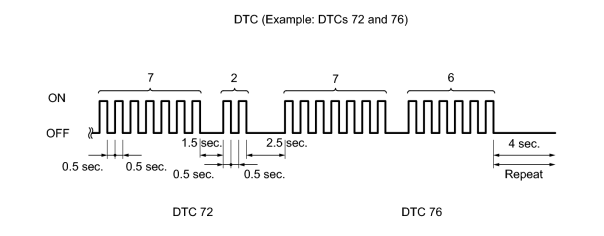
HINT:
- As an example, the blinking patterns for trouble codes 72 and 76 are shown above.
- Conditions are explained in Diagnostic Trouble Code chart.
- For the normal code, the light cycles between ON and OFF at intervals of 0.25 seconds.
- If more than 1 DTC is detected at the same time, the lowest numbered code will be displayed first.
(6) After the check, disconnect SST from terminals 13 (TC) and 4 (CG) of the DLC3.
(e) Check the yaw rate sensor.
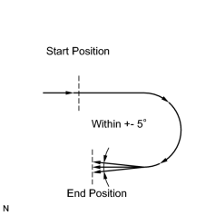
(1) Move the shift lever to D and drive the vehicle at the vehicle speed of approximately 5 km/h (3 mph). Turn the steering wheel either to left or right 90°or more, and drive the vehicle in a half-circle pattern.
(2) Stop the vehicle and move the shift lever to P. Check that the VSC buzzer sounds for 3 seconds.
If the VSC buzzer sounds, the sensor check has completed normally.
If the VSC buzzer does not sound, check the VSC buzzer circuit and check the sensor again.
If the VSC buzzer still does not sound, there is malfunction in the VSC sensor. Check the DTCs.
HINT:
- Drive the vehicle in a half-circle pattern. At the end of the turn, the direction of the vehicle should be within 180 +- 5°from its start position.
- Do not spin the wheels.
|
(3) Read the DTCs. |
|
(4) Using SST, connect terminals 13 (TC) and 4 (CG) of the DLC3.
SST: 09843-18040
(5) Read the number of blinks of the VSC TRAC warning light.
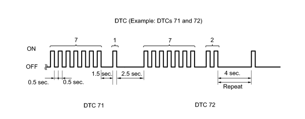
HINT:
- As an example, the blinking patterns for trouble codes 71 and 72 are shown above.
- Conditiosn are explained in Diagnostic Trouble Code chart.
- For the normal code, the light cycles between ON and OFF at intervals of 0.25 seconds.
- If more than 1 DTC is detected at the same time, the lowest numbered code will be displayed first.
(6) After the check, disconnect SST from terminals 13 (TC) and 4 (CG) of the DLC3.
3. CHECK SENSOR SIGNAL BY TEST MODE (When using Intelligent tester)
(a) Procedures for test mode:
(1) Turn the ignition switch OFF.
(2) Check that the shift lever is on P.
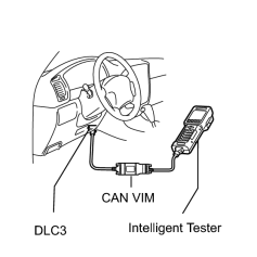
(3) Connect the intelligent tester (with CAN VIM) to the DLC3.
(4) Start the engine.
(5) Select the Test Mode following the intelligent tester screen.
HINT:
Refer to the intelligent tester operator's manual for further details.
|
(6) Check that the ABS warning light and VSC TRAC warning light blinks. HINT: If the ABS warning light and VSC TRAC warning light does not blink, check the ABS warning light circuit and VSC TRAC warning light circuit.
|
|
(7) Start the engine.
(b) Check the deceleration sensor.
(1) Create gravitational force (0.2 G or more) on the vehicle through deceleration. Use one of the following methods to decelerate the vehicle in the direction it is moving:
- Apply the brakes.
- Drive over a bump.
- Drive on an incline.
(2) When the deceleration is 0.2 G or more, check that the ABS warning light illuminates.
(c) Check the master cylinder pressure sensor.
(1) Leave the vehicle in a stationary condition and the brake pedal released for 1 second or more. Then quickly depress the brake pedal with a force of 98 N (10 kgf, 22 lbf) or more 1 second or more.
HINT:
At this time, the ABS warning light turns on for 3 second.
(d) Check the speed sensor.
(1) Drive the vehicle straight forward at the following speed. Then check the ABS warning light.
|
Vehicle Speed |
Check |
ABS Warning Light |
|---|---|---|
|
3 to 5 km/h (2 to 3 mph) |
Response of sensors |
Blinking |
|
45 km/h (28 mph) or higher |
Deviations of sensor signal |
Turns off |
HINT:
The sensor signal check may not complete if the vehicle's wheels slip or the steering wheel is turned during this check.
(2) Stop the vehicle.
(3) Read the DTCs.
|
(e) Check the yaw rate sensor. (1) Move the shift lever to D and drive the vehicle at the vehicle speed of approximately 5 km/h (3 mph). Turn the steering wheel either to left or right 90°or more, and drive the vehicle in a half-circle pattern. (2) Stop the vehicle and move the shift lever to P. Check that the VSC buzzer sounds for 3 seconds. If the VSC buzzer sounds, the sensor check has completed normally. If the VSC buzzer does not sound, check the VSC buzzer circuit, and check the sensor again. If the VSC buzzer still does not sound, there is malfunction in the VSC sensor. Check the DTCs. HINT:
(3) Read the DTCs. |
|
DTC of ABS sensor check function:
|
Code No. |
Diagnosis |
Trouble Area |
|---|---|---|
|
C1271/71 |
Low output voltage in right front speed sensor |
|
|
C1272/72 |
Low output voltage in left front speed sensor |
|
|
C1273/73 |
Low output voltage in right rear speed sensor |
|
|
C1274/74 |
Low output voltage in left rear speed sensor |
|
|
C1275/75 |
Abnormal change in output voltage of right front speed sensor |
Right front speed sensor rotor |
|
C1276/76 |
Abnormal change in output voltage of left front speed sensor |
Left front speed sensor rotor |
|
C1277/77 |
Abnormal change in output voltage of left front speed sensor |
Right rear speed sensor rotor |
|
C1278/78 |
Abnormal change in output voltage of left front speed sensor |
Left rear speed sensor rotor |
|
C1279/79 |
Deceleration sensor is faulty |
|
|
C1281/81 |
Master cylinder pressure sensor output signal is faulty |
Master cylinder pressure sensor |
|
C1282/82 |
Transfer indicator (center diff. lock) switch malfunction |
Transfer indicator (center diff. lock) switch |
|
C1283/83 |
Transfer L4 position switch malfunction |
Transfer L4 position switch |
HINT:
Read the number of blinks of the ABS warning light.
DTC of VSC sensor check function:
|
Code No. |
Diagnosis |
Trouble Area |
|---|---|---|
|
C0371/71 |
Yaw rate sensor output signal malfunction |
|
HINT:
Read the number of blinks of the VSC TRAC warning light.

|

|