- Vehicle speed is 19 mph (3 km/h) or more and voltage of ECU terminal IG remains below 9.5 V for more than 10 sec.
- While the condition that the solenoid relay is ON continues, ECU terminal IG1 voltage becomes 9.5 V or less, and the condition that the contact point of the solenoid relay is OFF continues for 0.2 sec. or more.
- The condition that ECU terminal IG1 voltage is more than 17.0 V continues for 1.2 sec. or more.
- While the solenoid relay outputs ON signal, ECU terminal IG1 voltage becomes more than 17.0 V, and the condition that the contact point of the solenoid relay is OFF continues for 0.2 sec. or more.
| Last Modified: 4-30-2014 | 6.6 C | Doc ID: RM000001A66002X |
| Model Year: 2006 | Model: LX470 | Prod Date Range: [05/2005 - ] |
| Title: BRAKE CONTROL: VEHICLE STABILITY CONTROL SYSTEM: C1241/41; Low Battery Positive Voltage or Abnormally High Battery Positive Voltage; 2006 MY LX470 [05/2005 - ] | ||
|
DTC |
C1241/41 |
Low Battery Positive Voltage or Abnormally High Battery Positive Voltage |
DESCRIPTION
|
DTC No. |
DTC Detection Condition |
Trouble Area |
|---|---|---|
|
C1241/41 |
Detection of any of the conditions 1. through 4.: |
|
WIRING DIAGRAM
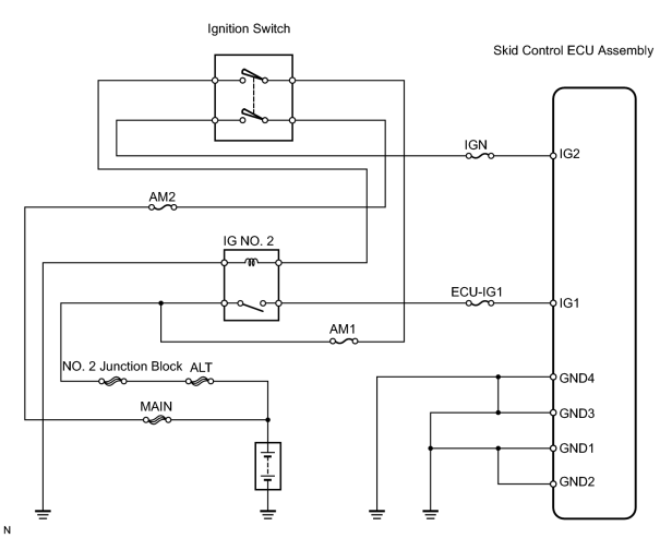
INSPECTION PROCEDURE
PROCEDURE
|
1. |
INSPECT FUSE (ECU-IG1) |
(a) Remove the ECU-IG1 fuse from the cowl side junction block LH.
(b) Measure the resistance of the fuse.
Standard resistance:
Below 1 Ω
| NG |

|
|

|
2. |
INSPECT BATTERY |
(a) Check the battery voltage.
Standard voltage:
11 to 14 V
Result
|
Result |
Proceed to |
|---|---|
|
Battery voltage is OK (when using intelligent tester) |
A |
|
Battery voltage is OK (when not using intelligent tester) |
B |
|
Battery voltage is abnormal |
C |
| B |
|
| C |
|
|
|
3. |
READ DATA LIST (IG VOLTAGE) |
(a) Check the DATA LIST for proper functioning of the IG voltage.
Skid control ECU assembly
|
Item |
Measurement Item / Range (Display) |
Normal Condition |
Diagnostic Note |
|---|---|---|---|
|
IG VOLTAGE |
ECU IG power voltage / UNDER or NORMAL or OVER |
- |
- |
OK:
Display is NORMAL
| OK |
|
|
|
4. |
CHECK WIRE HARNESS (SKID CONTROL ECU ASSEMBLY - BATTERY AND BODY GROUND) |
|
(a) Measure the voltage of the wire harness side connectors. Standard voltage:
(b) Measure the resistance of the wire harness side connectors. Standard resistance:
|
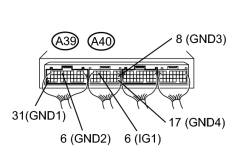
|
| NG |
|
| OK |
|

|

|