- At a vehicle speed of 6 mph (10 km/h) or more, when the condition that ECU terminal GL1 signal change range is less than 20 mV, and ECU terminal FL2 signal change range swings by 468 mV or more occurs for 30 sec. or more.
- At a vehicle speed of 6 mph (10 km/h) or more, when the condition that ECU terminal GL2 signal change range is less than 20 mV, and ECU terminal FL1 signal change range swings by 468 mV or more occurs for 30 sec. or more.
| Last Modified: 4-30-2014 | 6.6 C | Doc ID: RM000001A6F002X |
| Model Year: 2006 | Model: LX470 | Prod Date Range: [05/2005 - ] |
| Title: BRAKE CONTROL: VEHICLE STABILITY CONTROL SYSTEM: C1232/32; Stuck in Deceleration Sensor; 2006 MY LX470 [05/2005 - ] | ||
|
DTC |
C1232/32 |
Stuck in Deceleration Sensor |
DESCRIPTION
|
DTC No. |
DTC Detection Condition |
Trouble Area |
|---|---|---|
|
C1232/32 |
Detection of either of the conditions 1. or 2.: |
|
WIRING DIAGRAM
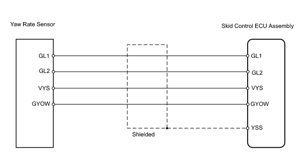
INSPECTION PROCEDURE
HINT:
When using the intelligent tester, start from *1. When not using the intelligent tester from *2.
PROCEDURE
|
1. |
READ VALUE USING INTELLIGENT TESTER (DECELERATION SENSOR)*1 |
(a) Check the DATA LIST for proper functioning of the deceleration sensor.
Skid control ECU assembly:
|
Item |
Measurement Item / Range (Display) |
Normal Condition |
Diagnostic Note |
|---|---|---|---|
|
DECELERAT SENS |
G sensor (GL1 filter) / Min.: -1.869 G, Max.: 1.869 |
Approximately 0 +- 0.13 G when vehicle is stationary |
Reading changes when vehicle is bounced |
|
DECELERAT SENS2 |
G sensor (GL2 filter) / Min.: -1.869 G, Max.: 1.869 |
Approximately 0 +- 0.13 G when vehicle is stationary |
Reading changes when vehicle is bounced |
OK:
Deceleration value changes.
| OK |

|
|

|
2. |
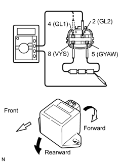
INSPECT YAW RATE SENSOR (INCLUDE DECELERATION SENSOR)*2 |
|
(a) Remove the console box and deceleration sensor. (b) Connect 3 dry cell batteries of 1.5 V in series. (c) Connect terminal 8 (VYS) to the batteries' positive (+) terminal and terminal 5 (GYAW) to the batteries' negative (-) terminal. Apply about 4.5 V between terminals 8 (VYS) and 5 (GYAW). NOTICE: Do not apply voltage of 6 V or more to terminals 8 ( VYS) and 5 (GYAW). (d) Measure the voltage when the sensor is tilted forward and rearward. Standard voltage:
HINT:
|
|
| NG |
|
|
|
3. |
CHECK WIRE HARNESS (SKID CONTROL ECU ASSEMBLY - YAW RATE SENSOR) |
| NG |
|
| OK |
|

|

|