- Battery
- Voltage regulator
- Power source circuit
| Last Modified: 4-30-2014 | 6.6 C | Doc ID: RM000001A6M002X |
| Model Year: 2006 | Model: LX470 | Prod Date Range: [05/2005 - ] |
| Title: BRAKE CONTROL: VEHICLE STABILITY CONTROL SYSTEM: C1242/42; IG2 Power Source Circuit; 2006 MY LX470 [05/2005 - ] | ||
|
DTC |
C1242/42 |
IG2 Power Source Circuit |
DESCRIPTION
|
DTC No. |
DTC Detection Condition |
Trouble Area |
|---|---|---|
|
C1242/42 |
With the vehicle running, open circuit in IG2 is detected for more than 7 sec. |
|
WIRING DIAGRAM
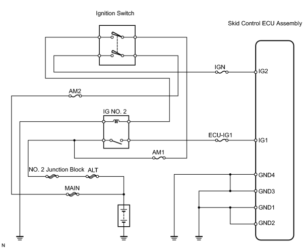
INSPECTION PROCEDURE
PROCEDURE
|
1. |
INSPECT FUSE (IGN) |
(a) Remove the IGN fuse from the cowl side junction block RH.
(b) Measure the resistance of the fuse.
Standard resistance:
Below 1 Ω
| NG |

|
|

|
2. |
INSPECT BATTERY |
(a) Check the battery voltage.
Standard voltage:
11 to 14 V
Result
|
Result |
Proceed to |
|---|---|
|
Battery voltage is OK (when using intelligent tester) |
A |
|
Battery voltage is OK (when not using intelligent tester) |
B |
|
Battery voltage is abnormal |
C |
| B |
|
| C |
|
|
|
3. |
DATA LIST (IG VOLTAGE) |
(a) Check the DATA LIST for proper function of the IG voltage.
Skid control ECU assembly
|
Item |
Measurement Item / Range (Display) |
Normal Condition |
Diagnostic Note |
|---|---|---|---|
|
IG VOLTAGE |
ECU IG power voltage / UNDER or NORMAL or OVER |
- |
- |
OK:
Display is NORMAL
| OK |
|
|
|
4. |
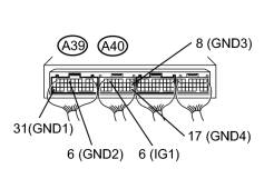
CHECK WIRE HARNESS (SKID CONTROL ECU ASSEMBLY - BATTERY AND BODY GROUND) |
|
(a) Measure the voltage of the wire harness side connectors. Standard voltage:
(b) Measure the resistance of the wire harness side connectors. Standard resistance:
|
|
| NG |
|
| OK |
|

|

|