| Last Modified: 4-30-2014 | 6.6 J | Doc ID: RM000001ABM000X |
| Model Year: 2006 | Model: LX470 | Prod Date Range: [05/2005 - ] |
| Title: PARK ASSIST / MONITORING: NIGHT VIEW SYSTEM: Night View Display Cover does not Open with Night View Switch and Night View Indicator Light does not Turn on; 2006 MY LX470 [05/2005 - ] | ||
|
Night View Display Cover does not Open with Night View Switch and Night View Indicator Light does not Turn on |
DESCRIPTION
This circuit checks that the power source of the night view system and each signal required to operate the indicator light are normally input to the night view ECU.
(Operating conditions:
![2006 MY LX470 [05/2005 - ]; PARK ASSIST / MONITORING: NIGHT VIEW SYSTEM: SYSTEM DESCRIPTION](../../../../stylegraphics/info.gif "2006 MY LX470 [05/2005 - ]; PARK ASSIST / MONITORING: NIGHT VIEW SYSTEM: SYSTEM DESCRIPTION") ).
).
NOTICE:
Do not apply grease to the sliding parts of the display cover.
WIRING DIAGRAM
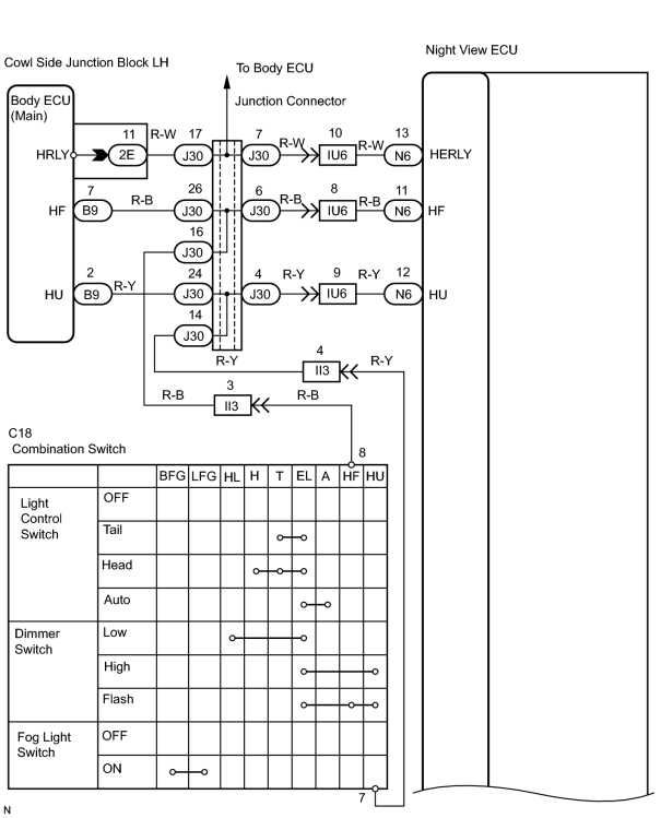
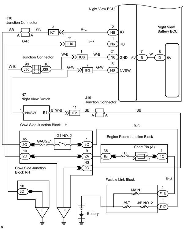
INSPECTION PROCEDURE
PROCEDURE
|
1. |
INSPECT FUSE (TEL, GAUGE1) |
(a) Remove the TEL and GAUGE1 fuses.
(b) Measure the resistance between terminals of the TEL and GAUGE1 fuses.
Standard resistance:
Below 1 Ω
| NG |

|
CHECK FOR SHORT CIRCUIT IN ALL HARNESS AND COMPONENTS CONNECTED TO TEL OR GAUGE1 FUSE. |
|

|
2. |
CHECK HEADLIGHT FUNCTION |
(a) Turn the headlight ON.
(b) Verify that all headlight functions are normal.
OK:
Headlight function is correct.
| NG |
|
|
|
3. |
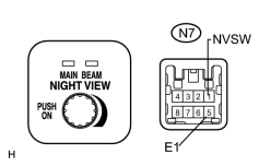
INSPECT NIGHT VIEW SWITCH |
|
(a) Remove the night view switch. (b) Measure the resistance between terminals NVSW and E1 of the night view switch. Standard resistance:
HINT: If OK, reinstall the night view switch. |
|
| NG |
|
|
|
4. |
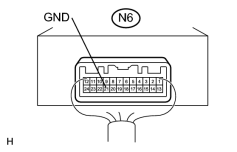
CHECK NIGHT VIEW ECU (GND RESISTANCE) |
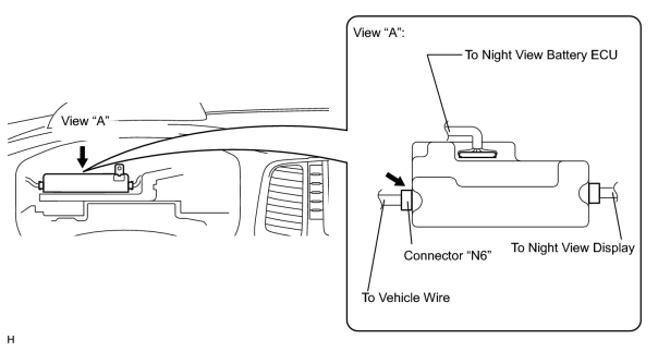
(a) Remove the combination meter assembly.
|
(b) Measure the resistance between terminal GND of the night view ECU connector "N6" and body ground.
(Terminals of ECU:
Standard resistance: Below 1 Ω |
|
| NG |
|
|
|
5. |
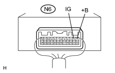
CHECK NIGHT VIEW ECU (IG, +B VOLTAGE) |
(a) Turn the ignition switch ON.
|
(b) Measure the voltage between terminal +B and IG of the night view ECU connector "N6" and body ground.
(Terminals of ECU:
Standard voltage: 10 to 14 V |
|
| NG |
|
REPAIR OR REPLACE HARNESS AND CONNECTOR (POWER SOURCE CIRCUIT) |
|
|
6. |
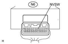
CHECK WIRE HARNESS (NIGHT VIEW ECU - BODY GROUND) |
(a) Disconnect the connector "N6" from the night view ECU.
(b) Turn the night view switch ON.
|
(c) Measure the resistance between terminal NVSW of night view ECU connector "N6" and body ground.
(Terminals of ECU:
Standard resistance:
HINT: If OK, reinstall the connector. |
|
| NG |
|
|
|
7. |
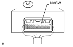
CHECK NIGHT VIEW ECU (NVSW VOLTAGE) |
(a) Turn the ignition switch ON.
(b) Turn the night view switch ON.
|
(c) Measure the voltage between terminal NVSW of the night view ECU connector "N6" and body ground.
(Terminals of ECU:
Standard voltage:
|
|
| OK |
|
|
|
8. |
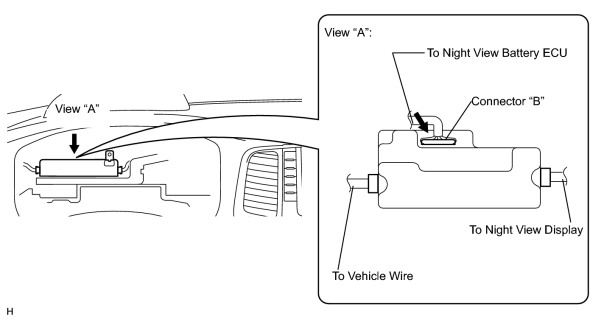
CHECK NIGHT VIEW ECU (5V VOLTAGE) |
(a) Turn the ignition switch ON.
|
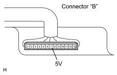
(b) Measure the voltage between terminal 5V of the night view ECU connector "B" and body ground.
(Terminals of ECU:
Standard voltage: 4.75 to 5.25 V |
|
| OK |
|
|
|
9. |
CHECK WIRE HARNESS (NIGHT VIEW BATTERY ECU - NIGHT VIEW ECU) |
(a) Remove the wire harness between the night view battery ECU and the night view ECU.
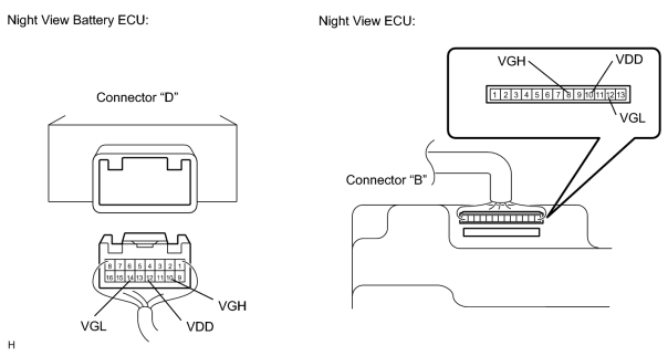
(b) Measure the resistance between terminals VGL, VDD, and VGH of connector "D" and those of "B".
(Terminals of ECU:
)
Standard resistance:
Below 1Ω
| NG |
|
| OK |
|
|
10. |
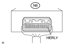
CHECK NIGHT VIEW ECU (HERLY VOLTAGE) |
(a) Turn the ignition switch ON.
(b) Turn the headlight ON.
|
(c) Measure the voltage between terminal HERLY of the night view ECU connector "N6" and body ground.
(Terminals of ECU:
Standard voltage:
|
|
| NG |
|
REPAIR OR REPLACE HARNESS AND CONNECTOR (NIGHT VIEW ECU - J30 CONNECTOR OF JUNCTION CONNECTOR) |
|
|
11. |
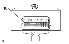
CHECK NIGHT VIEW ECU (HU VOLTAGE) |
(a) Turn the ignition switch ON.
(b) Turn the headlight ON.
|
(c) Measure the voltage between terminal HU of the night view ECU connector "N6" and body ground.
(Terminals of ECU:
Standard voltage:
|
|
| NG |
|
REPAIR OR REPLACE HARNESS AND CONNECTOR (NIGHT VIEW ECU - J30 CONNECTOR OF JUNCTION CONNECTOR) |
|
|
12. |
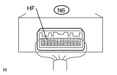
CHECK NIGHT VIEW ECU (HF VOLTAGE) |
(a) Turn the ignition switch ON.
(b) Turn the headlight ON.
|
(c) Measure the voltage between terminal HF of the night view ECU connector "N6" and body ground.
(Terminals of ECU:
Standard voltage:
|
|
| NG |
|
REPAIR OR REPLACE HARNESS AND CONNECTOR (NIGHT VIEW ECU - J30 CONNECTOR OF JUNCTION CONNECTOR) |
| OK |
|

|

|