| Last Modified: 4-30-2014 | 6.6 J | Doc ID: RM000001ABQ000X |
| Model Year: 2006 | Model: LX470 | Prod Date Range: [05/2005 - ] |
| Title: PARK ASSIST / MONITORING: NIGHT VIEW SYSTEM: Entire Image is White; 2006 MY LX470 [05/2005 - ] | ||
|
Entire Image is White |
DESCRIPTION
A white screen occurs by a malfunction of the night view camera or the night view display, and also by dirt on the windshield.
WIRING DIAGRAM
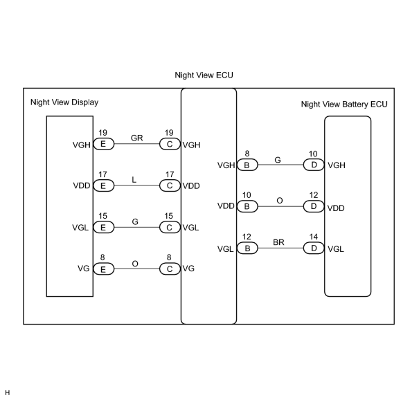
INSPECTION PROCEDURE
PROCEDURE
|
1. |
CHECK WINDSHIELD GLASS IN FRONT OF NIGHT VIEW CAMERA |
(a) Check the windshield glass in front of the night view camera.
OK:
Windshield glass is clean.
HINT:
Night view camera cleaning method
![2006 MY LX470 [05/2005 - ]; PARK ASSIST / MONITORING: NIGHT VIEW SYSTEM: ON-VEHICLE CLEANING+](../../../../stylegraphics/info.gif "2006 MY LX470 [05/2005 - ]; PARK ASSIST / MONITORING: NIGHT VIEW SYSTEM: ON-VEHICLE CLEANING+") .
.
| NG |

|
|

|
2. |
CHECK NIGHT VIEW CAMERA |
(a) Remove the over head junction (map light cover).
(b) Disconnect the connector from the night view camera.
(c) Connect SST to the wire harness of the night view camera on the body side as shown in the illustration.
SST: 09991-00610
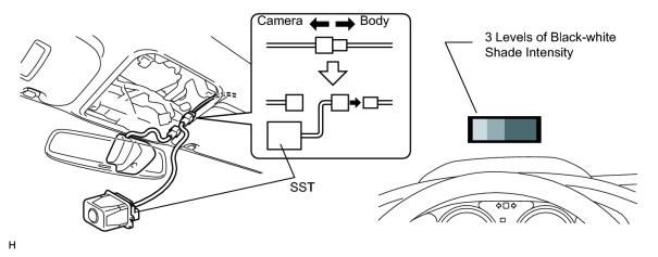
(d) Turn the ignition switch ON.
(e)
Switch to inspection mode
.
(f) Check the screen of the night view display.
OK:
3 levels of black-white shade intensity displayed.
| OK |
|
|
|
3. |
CHECK NIGHT VIEW ECU (VGL VOLTAGE) |
(a) Remove the combination meter assembly.
(b) Turn the ignition switch ON.
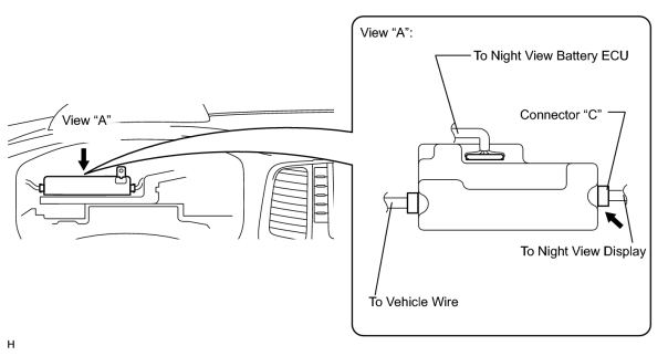
|
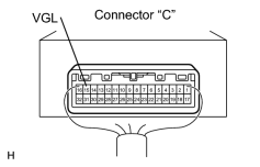
(c) Measure the voltage between terminal VGL of the night view ECU connector "C" and body ground.
(Terminals of ECU:
Standard voltage: -15 to -17 V HINT: Terminal voltage must meet the specified value within 20 seconds after ignition switch is ON. |
|
| NG |
|
|
|
4. |
CHECK NIGHT VIEW ECU (VDD VOLTAGE) |
(a) Turn the ignition switch ON.
|
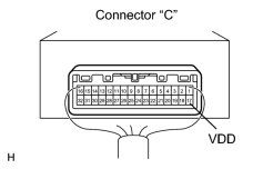
(b) Measure the voltage between terminal VDD of the night view ECU connector "C" and body ground.
(Terminals of ECU:
Standard voltage: 4.75 to 5.25 V HINT: Terminal voltage must meet the specified value within 20 seconds after ignition switch is ON. |
|
| NG |
|
|
|
5. |
CHECK NIGHT VIEW ECU (VGH VOLTAGE) |
(a) Turn the ignition switch ON.
|
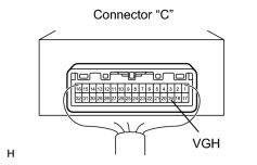
(b) Measure the voltage between terminal VGH of the night view ECU connector "C" and body ground.
(Terminals of ECU:
Standard voltage: 17.4 to 18.6 V HINT: Terminal voltage must meet the specified value within 20 seconds after ignition switch is ON. Result
HINT: *: If the symptom still occur after replacing night view, replace the night view display. |
|
| B |
|
| C |
|
|
|
6. |
CHECK NIGHT VIEW ECU (VG VOLTAGE) |
(a) Turn the ignition switch ON.
(b)
Switch to inspection mode
.
|
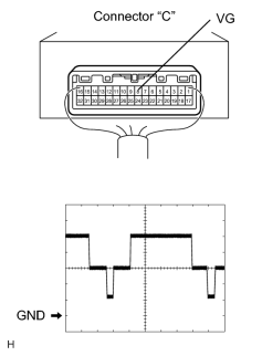
(c) Using an oscilloscope, check the output waveform between terminal VG of the night view ECU connector "C" and body ground.
(Terminals of ECU:
OK: The output waveform is as shown in the illustration. (Reference) oscilloscope condition
|
|
| NG |
|
| OK |
|
|
7. |
CHECK NIGHT VIEW ECU (VGL VOLTAGE) |
(a) Turn the ignition switch ON.
|
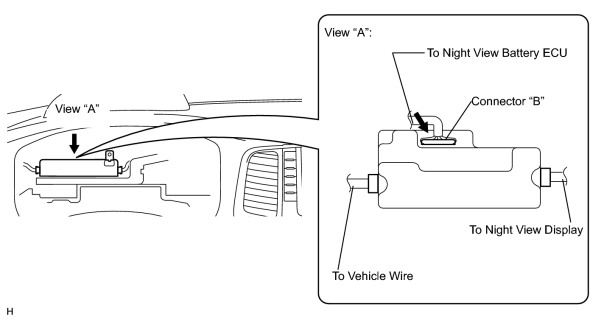
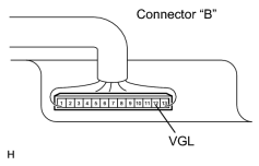
(b) Measure the voltage between terminal VGL of the night view ECU connector "B" and body ground.
(Terminals of ECU:
Standard voltage: -15 to -17 V HINT: Terminal voltage must meet the specified value within 20 seconds after ignition switch is ON. |
|
| NG |
|
|
|
8. |
CHECK NIGHT VIEW ECU (VDD VOLTAGE) |
(a) Turn the ignition switch ON.
|
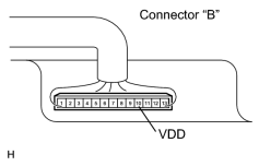
(b) Measure the voltage between terminal VDD of the night view ECU connector "B" and body ground.
(Terminals of ECU:
Standard voltage: 4.75 to 5.25 V HINT: Terminal voltage must meet the specified value within 20 seconds after ignition switch is ON. |
|
| NG |
|
|
|
9. |
CHECK NIGHT VIEW ECU (VGH VOLTAGE) |
(a) Turn the ignition switch ON.
|
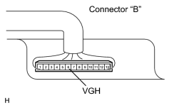
(b) Measure the voltage between terminal VGH of the night view ECU connector "B" and body ground.
(Terminals of ECU:
Standard voltage: 17.4 to 18.6 V HINT: Terminal voltage must meet the specified value within 20 seconds after ignition switch is ON. |
|
| OK |
|
|
|
10. |
CHECK WIRE HARNESS (NIGHT VIEW BATTERY ECU - NIGHT VIEW ECU) |
(a) Remove the wire harness between the night view battery ECU and the night view ECU.
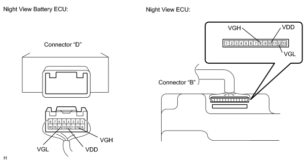
(b) Measure the resistance between terminals VGL, VDD, and VGH of connector "D" and those of "B".
(Terminals of ECU:
)
Standard resistance:
Below 1 Ω
| NG |
|
| OK |
|

|

|