| Last Modified: 4-30-2014 | 6.6 A | Doc ID: RM000001ACY001X |
| Model Year: 2006 | Model: LX470 | Prod Date Range: [05/2005 - ] |
| Title: DIFFERENTIAL: REAR DIFFERENTIAL CARRIER ASSEMBLY: REASSEMBLY; 2006 MY LX470 [05/2005 - ] | ||
REASSEMBLY
HINT:
- Using a cloth, clean off any foreign matter from the parts.
- Apply hypoid gear oil to all of the sliding and rotating surfaces with hypoid gear oil.
1. INSPECT SIDE GEAR BACKLASH
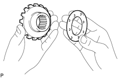
(a) Install the 2 thrust washers to the side gears.
(b) Install the side gear to the differential case.
(c) Install the 4 pinion gears and thrust washers to the spider.
(d) Install the spider assembly to the differential case.
HINT:
Install the spider to the differential case tightly.
|
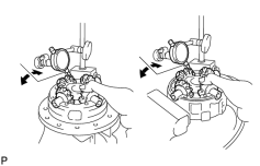
(e) Using a dial indicator, measure the side gear backlash holding the side gear and spider. Standard backlash: 0.02 to 0.15 mm (0.0008 to 0.0059 in.) HINT:
|
|
2. ASSEMBLE DIFFERENTIAL CASE
(a) Reinstall the spider to the differential case.
HINT:
Install the spider to the differential case tightly.
|
(b) Align the matchmarks and assemble the RH and LH differential cases. |

|
(c) Tighten the 8 bolts uniformly, a little at a time.
Torque:
47 N·m {480 kgf·cm, 35ft·lbf}
3. INSTALL REAR DIFFERENTIAL CASE BEARING
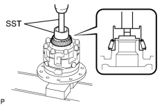
(a) Using SST and a press, install the RH side bearing on the differential case.
SST: 09710-30050
SST: 09950-70010
09951-07100
|
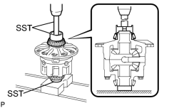
(b) Using SST and a press, install the LH side bearing on the differential case. SST: 09710-30050 SST: 09950-70010 09951-07100 SST: 09950-60010 09951-00480 |
|
4. INSTALL RING GEAR
(a) Clean the threads of the bolts and differential case with the white gasoline.
(b) Clean the contact surface of the differential case an ring gear.
|
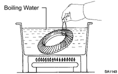
(c) Heat the ring gear to about 100°C (212°F) in boiling water. |
|
(d) Carefully take the ring gear out of the boiling water.
(e) After the moisture on the ring gear has completely evaporated, quickly install the ring gear to the differential case.
|
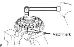
(f) Align the matchmarks on the ring gear and differential case. |
|
(g) Temporarily install the 12 set bolts.
(h) After the ring gear cools down enough, torque the 12 set bolts to which thread lock has been applied.
Thread lock:
Toyota Genuine Adhesive 1360K, Three Bond 1360K or Equivalent
Torque:
137 N·m {1,400 kgf·cm, 101ft·lbf}
5. INSPECT RING GEAR RUNOUT
(a) Place the bearing outer races on their respective bearings. Check that the right and left outer races are not interchanged.
(b) Install the differential case onto the carrier and tighten the adjusting nut just to the point where there is no play in the bearings.
|
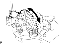
(c) Using a dial indicator, check the ring gear runout. Maximum runout: 0.05 mm (0.0020 in.) |
|
(d) Remove the differential case.
|
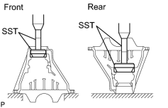
6. INSTALL BEARING OUTER RACE (a) Using SST and a press, install the front bearing outer race. SST: 09950-60020 09951-00710 SST: 09950-70010 09951-07150 (b) Using SST and a press, install the rear bearing outer race. SST: 09950-60020 09951-00890 SST: 09950-70010 09951-07150 |
|
7. INSTALL REAR DRIVE PINION REAR TAPERED ROLLER BEARING
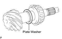
(a) Install the plate washer on the drive pinion.
HINT:
First fit a washer with the same thickness as the washer that was removed. then after checking the tooth contact pattern, replace the washer with one of a different thickness if necessary.
|
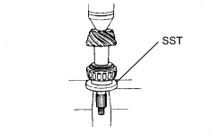
(b) Using SST and a press, install the rear bearing onto the drive pinion. SST: 09506-35010 |
|
8. TEMPORARILY ADJUST DRIVE PINION PRELOAD
(a) Install the drive pinion and front bearing.
HINT:
Assemble the spacer and oil seal after adjusting the gear contact pattern.
(b) Install the oil slinger.
|
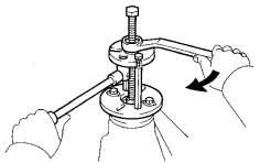
(c) Install the companion flange with SST. SST: 09950-30012 09951-03010 09953-03010 09954-03010 09955-03030 09956-03040 |
|
|
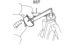
(d) Using SST to hold the flange and adjust the drive pinion preload by tightening the companion flange nut. SST: 09330-00021 NOTICE:
|
|
|
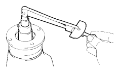
(e) Using a torque wrench, measure the preload. Standard preload (at start of torque):
HINT: Measure the total preload after turning the bearing clockwise and counterclockwise several times to make the bearing smooth. |
|
9. INSTALL DIFFERENTIAL CASE IN CARRIER
(a) Place the 2 bearing outer races on their respective bearings. Make sure that the right and left outer races are not interchanged.
(b) Install the differential case in the carrier.
HINT:
Make sure that there is backlash between the ring gear and drive pinion.
|
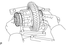
10. INSTALL REAR DIFFERENTIAL BEARING ADJUSTING NUT (a) Install the 2 bearing nuts on the carrier, making sure the nuts are engaged properly. |
|
|
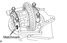
11. INSTALL BEARING CAP (a) Align the matchmarks on the bearing cap and carrier. Screw in the 2 bearing cap bolts 2 or 3 turns and press down the bearing cap by hand. HINT: If the bearing cap does fit not tightly on the carrier, the adjusting nuts are not engaged properly. Reinstall the adjusting nut if necessary. |
|
12. ADJUST SIDE BEARING PRELOAD
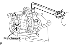
(a) Torque the 4 bolts.
Torque:
83 N·m {850 kgf·cm, 61ft·lbf}
|
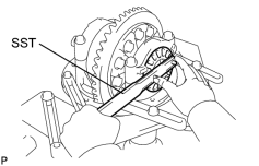
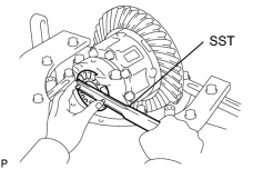
(b) Then loosen them to the point where the adjusting nuts can be turned by SST. SST: 09504-00011 |
|
(c) Tighten the 4 bolts.
Torque:
9.8 N·m {100 kgf·cm, 7ft·lbf}
(d) Using SST, torque the adjusting nut on the ring gear side until the ring gear has a backlash of about 0.2 mm (.008 in.).
|
(e) While turning the ring gear, use the SST to fully tighten the adjusting nut on the drive pinion side. After the bearings are settled, loosen the adjusting nut on the drive pinion side. |
|
|
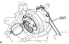
(f) Place the dial indicator on the top of the adjusting nut on the ring gear side. |
|
(g) Adjust the side bearing to zero preload by tightening the other adjusting nut until the pointer on the indicator bearings move.
|
(h) Using SST, torque the adjusting nut 1 to 1.5 notches from the zero preload position. |
|
|
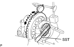
(i) Using a dial indicator, adjust the ring gear backlash until it is within the specified value. Standard backlash: 0.13 to 0.18 mm (0.0051 to 0.0071 in.) HINT: The backlash is adjusted by turning the right and left adjusting nuts by an equal amount. For example, loosen the nut on the left side 1 notch and torque the nut on the right side 1 notch. |
|
|
(j) Torque the 4 bearing cap bolts. Torque: 83 N·m {850 kgf·cm, 61ft·lbf} |
|
(k) After rotating the ring gear 5 turns or more, recheck the ring gear backlash.
Standard backlash:
0.13 to 0.18 mm (0.0051 to 0.0071 in.)
|
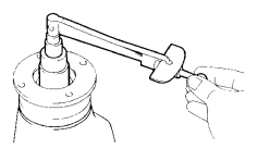
13. INSPECT TOTAL PRELOAD (a) Using a torque wrench, measure the preload with the teeth of the drive pinion and ring gear in contact. Torque: Standard preload (at start of torque) - 0.38 to 0.63 N·m {3.9 to6.5 kgf·cm, 3.3 to 5.6in·lbf} + drive pinion |
|
14. INSPECT TOOTH CONTACT BETWEEN RING GEAR AND DRIVE PINION
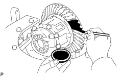
(a) Coat 3 or 4 teeth at 3 different positions on the ring gear with red lead primer.
(b) Turn the companion flange, in both directions to inspect the ring gear for proper tooth contact.
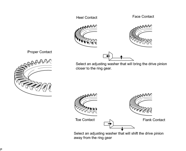
-
If the teeth are not contacting properly, use the following table to select a proper washer for correction.
Standard plate washer thickness:
Thickness mm (in.)
Thickness mm (in.)
1.050 (0.04134)
1.325 (0.05217)
1.075 (0.04232)
1.350 (0.05315)
1.100 (0.04331)
1.375 (0.05413)
1.125 (0.04429)
1.400 (0.05512)
1.150 (0.04528)
1.425 (0.05610)
1.175 (0.04626)
1.450 (0.05709)
1.200 (0.04724)
1.475 (0.05807)
1.225 (0.04823)
1.500 (0.05906)
1.250 (0.04921)
1.525 (0.06004)
1.275 (0.05020)
1.550 (0.06102)
1.300 (0.05118)
-
15.
REMOVE DRIVE PINION COMPANION FLANGE SUB-ASSEMBLY
![2006 MY LX470 [05/2005 - ]; DIFFERENTIAL: REAR DIFFERENTIAL CARRIER ASSEMBLY: DISASSEMBLY+](../../../../stylegraphics/info.gif "2006 MY LX470 [05/2005 - ]; DIFFERENTIAL: REAR DIFFERENTIAL CARRIER ASSEMBLY: DISASSEMBLY+")
16.
REMOVE REAR DIFFERENTIAL DRIVE PINION OIL SLINGER
17.
REMOVE REAR DRIVE PINION FRONT TAPERED ROLLER BEARING
|
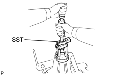
18. REMOVE BEARING OUTER RACE (a) Using SST, remove the bearing outer race. SST: 09308-00010 |
|
19. INSTALL REAR DIFFERENTIAL DRIVE PINION BEARING SPACER
|
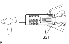
20. INSTALL BEARING OUTER RACE (a) Using SST and a hammer, install the bearing outer race. SST: 09316-60011 09316-00011 09316-00021 |
|
21. INSTALL REAR DRIVE PINION FRONT TAPERED ROLLER BEARING
22. INSTALL REAR DIFFERENTIAL DRIVE PINION OIL SLINGER
23. INSTALL REAR DIFFERENTIAL CARRIER OIL SEAL
(a) Coat a new oil seal periphery with hypoid gear oil.
|
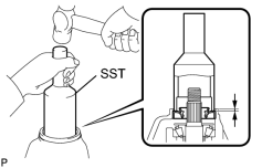
(b) Using SST and a hammer, install the oil seal. SST: 09214-76011 Standard depth: 0.5 mm (0.020 in.) |
|
(c) Coat the lip of the oil seal with MP grease.
24. INSTALL REAR DRIVE PINION COMPANION FLANGE SUB-ASSEMBLY
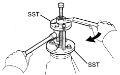
(a) Using SST, install the companion flange.
SST: 09950-30012
09951-03010
09953-03010
09954-03010
09955-03030
09956-03040
(b) Coat the threads of a new nut with gear oil.
|
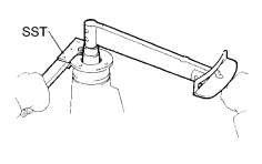
(c) Using SST to hold the flange, install the nut. SST: 09330-00021 Torque: 245 N·m {2,500 kgf·cm, 181ft·lbf} |
|
25. ADJUST DRIVE PINION PRELOAD
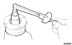
(a) Using a torque wrench, measure the preload of the backlash between the drive pinion and ring gear.
Standard preload (at start of torque):
|
Bearing |
Preload |
|---|---|
|
New bearing |
1.36 to 1.90 N*m (13.9 to 19.4 kgf*cm, 12.0 to 16.8 in.*lbf) |
|
Reused bearing |
0.71 to 0.99 N*m (7.2 to 10.1 kgf*cm, 6.3 to 8.8 in.*lbf) |
- If the preload is greater than the specified value, replace the bearing spacer.
|
(b) If the preload is less than the specified value, retighten the nut with a force of 13 N*m (130 kgf*cm, 9 ft.*lbf) at a time until the specified preload is reached. SST: 09330-00021 Torque: 441 N·m {4,500 kgf·cm, 326ft·lbf} or less
|
|
26.
INSPECT RING GEAR BACKLASH
27. INSPECT TOOTH CONTACT BETWEEN RING GEAR AND DRIVE PINION
28.
INSPECT RUNOUT OF REAR DRIVE PINION COMPANION FLANGE SUB-ASSEMBLY
29. STAKE DRIVE PINION NUT
30. INSTALL REAR DIFFERENTIAL BEARING ADJUSTING NUT LOCK
(a) Install 2 new nut locks on the bearing caps.
(b) Tighten the 2 bolts and bend the 2 nut locks.
Torque:
13 N·m {130 kgf·cm, 9ft·lbf}

|

|