| Last Modified: 4-30-2014 | 6.6 A | Doc ID: RM000001ATU000X |
| Model Year: 2006 | Model: LX470 | Prod Date Range: [05/2005 - ] |
| Title: INSTRUMENT PANEL: INSTRUMENT PANEL SAFETY PAD: INSTALLATION; 2006 MY LX470 [05/2005 - ] | ||
INSTALLATION
1. INSTALL INSTRUMENT PANEL REINFORCEMENT ASSEMBLY
2. INSTALL NO. 2 NIGHT VIEW ECU (w/ Night View System)
(a) Install the ECU with the 2 screws.
3. INSTALL NO. 1 INSTRUMENT PANEL BRACE SUB-ASSEMBLY
4. INSTALL INSTRUMENT PANEL TO FLOOR BRACE SUB-ASSEMBLY
5. INSTALL GLOVE COMPARTMENT DOOR DAMPER
6. INSTALL NO. 4 HEATER TO REGISTER DUCT
7. INSTALL NO. 3 HEATER TO REGISTER DUCT
8. INSTALL ECM
|
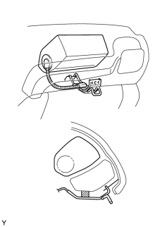
9. INSTALL INSTRUMENT PANEL SAFETY PAD SUB-ASSEMBLY HINT:
(a) Install the 6 bolts, 2 nuts and instrument panel, then connect the connectors. (b) Install the 2 bolts to the front passenger airbag assembly. Torque: 20 N·m {204 kgf·cm, 15ft·lbf} (c) Connect the junction connectors. HINT: The connectors can be connected by tightening the bolts. |
|
|
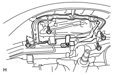
10. INSTALL NIGHT VIEW DISPLAY (w/ Night View System) (a) Install the display with the 4 screws. |
|
|
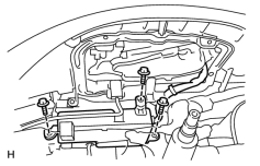
11. INSTALL NIGHT VIEW CONTROL ECU (w/ Night View System) (a) Connect the connectors to the ECU. (b) Install the ECU with the 3 bolts. |
|
|
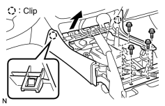
12. INSTALL FRONT CONSOLE BOX (a) Install the console box and No. 4 console box mounting bracket with the 4 bolts. |
|
13. INSTALL FRONT ASH RECEPTACLE RETAINER
(a) Install the ash receptacle retainer with the 2 screws.
(b) Install the ash receptacle box.
|
14. INSTALL INSTRUMENT CLUSTER FINISH PANEL CENTER LOWER (a) Connect the connectors. (b) Attach the 5 clips to install the finish panel. |
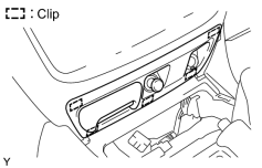
|
|
15. INSTALL REAR CONSOLE BOX SUB-ASSEMBLY (w/o Disc Player Changer, w/o LEXUS Link System) (a) Install the console box with the 4 bolts and the 4 screws. |
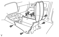
|
|
16. INSTALL REAR CONSOLE BOX SUB-ASSEMBLY (w/ Disc Player Changer) (a) Install the console box with the 2 bolts and the 6 screws. |
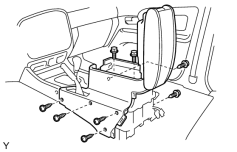
|
|
17. INSTALL REAR CONSOLE BOX SUB-ASSEMBLY (w/ LEXUS Link System) (a) Install the console box with the 2 nuts and the 6 screws. |
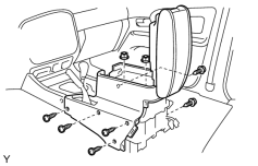
|
18. INSTALL RADIO RECEIVER CONTROL PANEL
(a) Install the rear radio control panel with the 3 screws, and connect the connector.
|
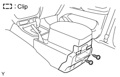
19. INSTALL REAR CONSOLE END PANEL SUB-ASSEMBLY (a) Attach the 2 clips to install the end panel. (b) Install the 2 screws. (c) Install the console cup holder box. |
|
20. INSTALL UPPER CONSOLE PANEL SUB-ASSEMBLY
(a) Install the upper console panel, and then install the transfer shift lever knob.
21. INSTALL INSTRUMENT PANEL FINISH PANEL LH LOWER
(a) Install the finish panel with the 3 screws.
|
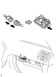
22. CONNECT AIRBAG CONNECTOR |
|
|
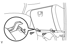
23. INSTALL GLOVE COMPARTMENT DOOR SUB-ASSEMBLY (a) Install the glove compartment door, and connect the glove compartment door damper clip. (b) Install the 2 screws. |
|
24. INSTALL COMBINATION METER
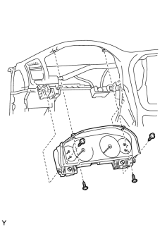
(a) Check that the set-in connectors are connected in the installation holes on the instrument panel securely.
(b) Place the combination meter on the instrument panel.
(c) Install the combination meter by tightening the screws.
|
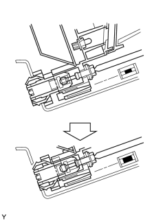
(d) Tighten the connection bolts. HINT:
NOTICE: Follow the procedures in the correct order. Otherwise, the set-in connectors on the wire harness side and on the meter side might not be connected properly. |
|
|
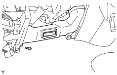
25. INSTALL NO. 2 HEATER TO REGISTER DUCT (a) Install the No. 2 heater to register duct with the screw. (b) Install the No. 1 transceiver finish plate assembly with the screw, and connect the connector. |
|
|
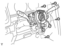
26. INSTALL COMBINATION SWITCH ASSEMBLY (a) Install the combination switch with the 4 screws. (b) Install the clamp, and then connect the connectors. |
|
27. INSTALL STEERING COLUMN COVER
(a) Install the column covers with the 3 screws.
28. INSTALL LH LOWER PANEL
(a) Install the LH lower panel with the 3 bolts.
|
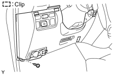
29. INSTALL NO. 1 LOWER PANEL (a) Connect the connectors. (b) Attach the 5 clips to install the No. 1 lower panel with the screw. |
|
30. INSTALL FUEL LID OPEN LEVER SUB-ASSEMBLY
(a) Install the control cable lever with the 2 screws.
31. INSTALL HOOD LOCK CONTROL LEVER SUB-ASSEMBLY
(a) Install the control cable with the 2 screws.
|
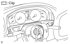
32. INSTALL INSTRUMENT CLUSTER FINISH PANEL SUB-ASSEMBLY (a) Connect the connector. (b) Attach the 2 clips to install the finish panel. |
|
33.
INSTALL STEERING WHEEL ASSEMBLY
![2006 MY LX470 [05/2005 - ]; STEERING COLUMN: STEERING COLUMN ASSEMBLY: INSTALLATION+](../../../../stylegraphics/info.gif "2006 MY LX470 [05/2005 - ]; STEERING COLUMN: STEERING COLUMN ASSEMBLY: INSTALLATION+")
34.
INSTALL STEERING PAD ASSEMBLY
|
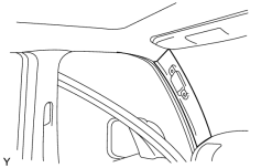
35. INSTALL FRONT PILLAR GARNISH RH (a) Install the garnish. (b) Install the assist grip with the 2 screws, and then install the 2 assist grip plugs. |
|
36. INSTALL FRONT PILLAR GARNISH LH
HINT:
Use the same procedures described for the RH side.
37. INSTALL FRONT DOOR OPENING TRIM WEATHERSTRIP RH
38. INSTALL FRONT DOOR OPENING TRIM WEATHERSTRIP LH
39. INSTALL COWL SIDE TRIM BOARD RH
40. INSTALL COWL SIDE TRIM BOARD LH
41. INSTALL FRONT DOOR SCUFF PLATE LH
42. INSTALL FRONT DOOR SCUFF PLATE RH
|
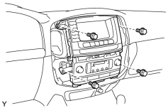
43. INSTALL RADIO WITH AIR CONDITIONING CONTROL ASSEMBLY (a) Install the radio with air conditioning control with the 4 bolts. |
|
44. INSTALL NO. 3 INSTRUMENT PANEL REGISTER ASSEMBLY
(a) Attach the 3 clips to install the register.
45. INSTALL NO. 2 INSTRUMENT PANEL REGISTER ASSEMBLY
(a) Attach the 3 clips to install the register.
46. INSTALL INSTRUMENT CLUSTER FINISH PANEL CENTER
(a) Connect the connectors.
(b) Attach the 6 clips to install the finish panel.
47. CONNECT CABLE TO NEGATIVE BATTERY TERMINAL
48. PERFORM INITIALIZATION
(a)
Perform initialization
.
NOTICE:
Certain systems need to be initialized after disconnecting and reconnecting the cable from the negative (-) battery terminal.
49. CHECK SRS WARNING LIGHT
(a)
Check the SRS warning light
.

|

|