- Steering angle sensor
- Steering angle sensor circuit
- VGRS ECU
- Skid control ECU
| Last Modified: 4-30-2014 | 6.6 C | Doc ID: RM000001BBG000X |
| Model Year: 2006 | Model: LX470 | Prod Date Range: [05/2005 - ] |
| Title: STEERING COLUMN: VARIABLE GEAR RATIO STEERING SYSTEM: C1511/11; Torque Sensor 1 Malfunction; 2006 MY LX470 [05/2005 - ] | ||
|
DTC |
C1511/11 |
Torque Sensor 1 Malfunction |
DESCRIPTION
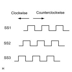
The VGRS ECU receives the steering sensor signals (SS1, SS2, SS3), and judges the steering condition to drive the VGRS actuator.
When the steering sensor signal is abnormal, the VGRS ECU records the DTC and illuminates the VGRS warning light.
|
DTC No. |
DTC Detection Condition |
Trouble Area |
|---|---|---|
|
C1511/11 |
The system detects a momentary interruption of the steering angle sensor signal (SS1, SS2, SS3) 10 times, or an open circuit for more than 0.12 sec. |
|
WIRING DIAGRAM
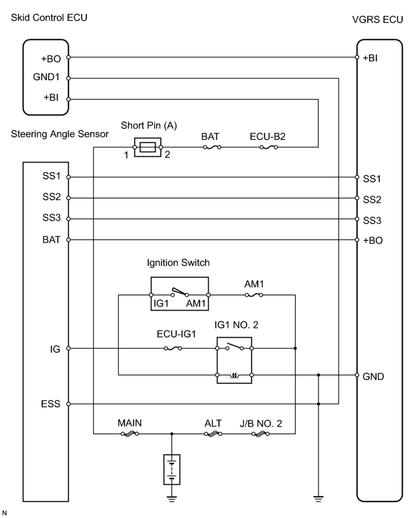
INSPECTION PROCEDURE
HINT:
- Determine the trouble area by checking the steering sensor signal using the intelligent tester.
- When not using the intelligent tester, go to *.
PROCEDURE
|
1. |
READ VALUE USING INTELLIGENT TESTER |
(a) Connect the intelligent tester (with CAN VIM) to the DLC3.
(b) Start the engine.
(c) Using the intelligent tester, display the DATA LIST.
(d) Check each steering sensor signal (SS1, SS2, SS3) while slowly turning the steering wheel.
OK:
STR SENS1: High or Low
STR SENS2: High or Low
STR SENS3: High or Low
Result
|
Result |
Proceed to |
|---|---|
|
All OK |
A |
|
All NG |
B |
|
Other |
C |
| A |

|
| C |
|
|

|
2. |
INSPECT POWER SUPPLY VOLTAGE OF STEERING ANGLE SENSOR |
HINT:
- When a malfunction is found in the power supply voltage of the steering angle sensor, the sensor outputs become abnormal.
- The power supply has 2 systems, IG and BAT.
(a) Turn the ignition switch OFF.
(b) Disconnect the C36 steering angle sensor connector.
(c) Turn the ignition switch ON.
|
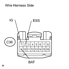
(d) Measure the voltage between terminals C36-1 (IG) and C36-2 (ESS) of the steering angle sensor harness side connector. |
|
(e) Measure the voltage between terminals C36-9 (BAT) and C36-2 (ESS) of the steering angle sensor harness side connector.
Standard voltage:
10 to 14 V
Result
|
Result |
Proceed to |
|---|---|
|
OK |
A |
|
NG (IG power supply terminals 1 and 2) |
B |
|
NG (BAT power supply terminals 9 and 2) |
C |
| B |
|
| C |
|
|
|
3. |
INSPECT OUTPUT OF STEERING ANGLE SENSOR * |
HINT:
Check the output when slowly turning the steering wheel to judge whether or not the sensor is normal.
(a) Turn the ignition switch OFF.
(b) Disconnect the V11 VGRS ECU connector.
(c) Turn the ignition switch ON.
|
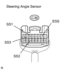
(d) When slowly turning the steering wheel, measure the resistance between terminals of the C36 steering angle sensor connector. Standard resistance:
|
|
| OK |
|
| NG |
|
|
4. |
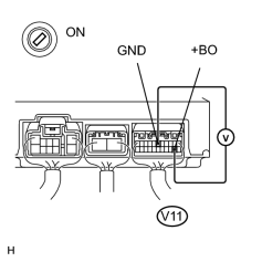
CHECK VOLTAGE BETWEEN TERMINALS +BO AND GND OF VGRS ECU |
|
(a) Turn the ignition switch ON. (b) Measure the voltage between terminals V11-13 (+BO) and V11-6 (GND) of the V11 VGRS ECU. Standard voltage: 10 to 14 V |
|
| OK |
|
REPAIR OR REPLACE HARNESS AND CONNECTOR (STEERING ANGLE SENSOR - VGRS ECU) |
|
|
5. |
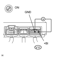
CHECK VOLTAGE BETWEEN TERMINALS +BI AND GND OF VGRS ECU |
|
(a) Turn the ignition switch ON. (b) Measure the voltage between terminals V11-2 (+BI) and V11-6 (GND) of the VGRS ECU. Standard voltage: 10 to 14 V |
|
| OK |
|
|
|
6. |
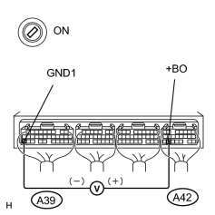
CHECK VOLTAGE BETWEEN TERMINALS +BO AND GND OF SKID CONTROL ECU |
|
(a) Turn the ignition switch ON. (b) Measure the voltage between terminals A42-21 (+BO) and A39-31 (GND1) of the skid control ECU. Standard voltage: 10 to 14 V |
|
| OK |
|
REPAIR OR REPLACE HARNESS AND CONNECTOR (SKID CONTROL ECU - VGRS ECU) |
|
|
7. |
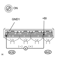
CHECK VOLTAGE BETWEEN TERMINALS +BI AND GND OF SKID CONTROL ECU |
|
(a) Turn the ignition switch ON. (b) Measure the voltage between terminals A42-15 (+BI) and A39-31 (GND1) of the skid control ECU. Standard voltage: 10 to 14 V |
|
| OK |
|
| NG |
|
|
8. |
CHECK WIRE HARNESS (STEERING ANGLE SENSOR - VGRS ECU) |
(a) Turn the ignition switch OFF.
(b) Disconnect the C36 steering angle sensor connector and V11 VGRS ECU connector.
|
(c) Check the continuity between each of terminal C36-6 (SS1) - V11-4, C36-14 (SS2) - V11-15 and C36-7 (SS3) - V11-5 of the steering angle sensor connector and the VGRS ECU connectors. OK: Continuity |
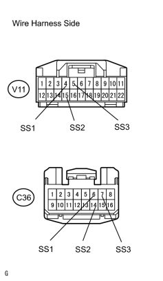
|
(d) Check the continuity between each of terminal V11-4 (SS1), V11-5 (SS2) and V11-5 (SS3) of the VGRS ECU connector and body ground.
OK:
No Continuity
| NG |
|
| OK |
|

|

|