| Last Modified: 4-30-2014 | 6.6 J | Doc ID: RM000001BBX000X |
| Model Year: 2006 | Model: LX470 | Prod Date Range: [05/2005 - ] |
| Title: STEERING COLUMN: VARIABLE GEAR RATIO STEERING SYSTEM: TS and CG Terminal Circuit; 2006 MY LX470 [05/2005 - ] | ||
|
TS and CG Terminal Circuit |
DESCRIPTION
The sensor signal check detects faults in VGRS sensor signal, which cannot be detected by the DTC check.
HINT:
If a current DTC exists when connecting TS and CG, the warning light will remain on.
WIRING DIAGRAM
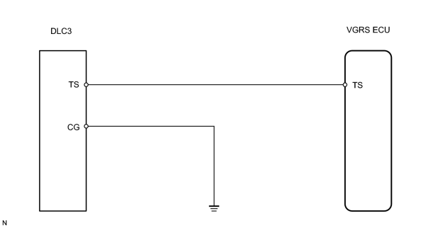
INSPECTION PROCEDURE
PROCEDURE
|
1. |
CHECK WIRE HARNESS (VGRS ECU - DLC3 AND BODY GROUND) |
|
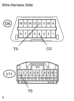
(a) Disconnect the V11 VGRS ECU connector. (b) Measure the resistance according to the values in the table below. Standard resistance:
|
|
| NG |

|
| OK |
|

|

|