| Last Modified: 4-30-2014 | 6.6 J | Doc ID: RM000001BCA000X |
| Model Year: 2006 | Model: LX470 | Prod Date Range: [05/2005 - ] |
| Title: SLIDING ROOF: SLIDING ROOF SYSTEM: ECU Power Source Circuit; 2006 MY LX470 [05/2005 - ] | ||
|
ECU Power Source Circuit |
DESCRIPTION
This is the power source for the ECU and sliding roof gear.
WIRING DIAGRAM
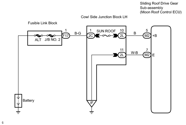
INSPECTION PROCEDURE
PROCEDURE
|
1. |
CHOOSE DIAGNOSIS METHOD |
(a) Choose the diagnosis method.
|
Result |
Proceed to |
|---|---|
|
Using intelligent tester |
A |
|
Not using intelligent tester |
B |
| B |

|
|

|
2. |
PERFORM ACTIVE TEST BY INTELLIGENT TESTER |
(a) Connect the intelligent tester (with CAN VIM) to the DLC3.
(b) Enter into the ACTIVE TEST mode of the intelligent tester.
(c) Check that "Slide roof motor" operates according to the intelligent tester commands.
NOTICE:
Caution is necessary not to be caught in the roof glass because the jam protection system does not operate during the ACTIVE TEST.
HINT:
With one ACTIVE TEST operaytion, the sliding roof can be slid and tilted continuously.
OK:
The slide roof operates normally.
| OK |
|
PROCEED TO NEXT CIRCUIT INSPECTION SHOWN ON PROBLEM SYMPTOMS TABLE |
|
|
3. |
INSPECT FUSE (SUN ROOF) |
(a) Measure the resistance of the SUN ROOF fuse.
Standard resistance:
Below 1 Ω
| NG |
|
|
|
4. |
CHECK WIRE HARNESS (SLIDING ROOF DRIVE GEAR SUB-ASSEMBLY - BODY GROUND) |
| NG |
|
|
|
5. |
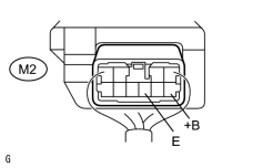
CHECK SLIDING ROOF DRIVE GEAR SUB-ASSEMBLY (+B VOLTAGE) |
|
(a) Turn the ignition switch OFF. (b) Measure the voltage between terminal +B and GND of the ECU with the connector connected. Standard voltage:
|
|
| NG |
|
| OK |
|
PROCEED TO NEXT CIRCUIT INSPECTION SHOW ON PROBLEM SYMPTOMS TABLE |

|

|