| Last Modified: 4-30-2014 | 6.6 A | Doc ID: RM000001BJ8001X |
| Model Year: 2006 | Model: LX470 | Prod Date Range: [05/2005 - ] |
| Title: TIRE AND WHEEL: TIRE PRESSURE WARNING VALVE AND TRANSMITTER: REPLACEMENT; 2006 MY LX470 [05/2005 - ] | ||
REPLACEMENT
1. REMOVE FRONT TIRE
2. REMOVE REAR TIRE
3. REMOVE TIRE PRESSURE MONITOR VALVE SUB-ASSEMBLY
(a) Remove the valve core and cap, and release air from the tire.
(b) After ensuring that air is sufficiently released, remove the nut and washer that are used to fix the tire pressure monitor valve and drop the valve sensor inside the tire.
HINT:
Keep the removed cap, valve core, nut and washer.
|
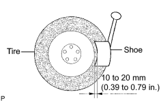
(c) After dropping the tire pressure monitor valve into the tire, disengage the bead using the shoe of the tire remover. NOTICE: Be careful not to damage the tire pressure monitor valve because of interference between the sensor and tire bead. |
|
(d) Remove the bead on the upper side.
(e) Take out the valve sensor from the tire and remove the bead on the valve.
HINT:
Check that there are no cracks or damage on the grommet. If any damage is found, replace the grommet together with the washer and nut.
4. INSTALL TIRE PRESSURE MONITOR VALVE SUB-ASSEMBLY
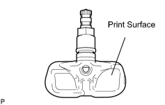
(a) Insert the tire pressure monitor valve into the valve installation hole. Insert it from the inside of the rim so that the print surface can be seen.
NOTICE:
- Check that there is no visible deformation, damage or other abnormalities on the transmitter.
- Check that there is no foreign matter on the inner grommet and around the rim hole.
- If installed in the reverse direction, the tire pressure monitor valve may be damaged or fail to transmit signals when running at high speed.
- If installing a new tire pressure monitor valve, write down the ID number before installation.
-
It is necessary to register the ID in the ECU after installation
![2006 MY LX470 [05/2005 - ]; TIRE AND WHEEL: TIRE PRESSURE WARNING SYSTEM: REGISTRATION](../../../../stylegraphics/info.gif "2006 MY LX470 [05/2005 - ]; TIRE AND WHEEL: TIRE PRESSURE WARNING SYSTEM: REGISTRATION") .
.
|
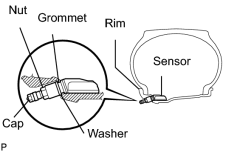
(b) Install the washer on the tire pressure monitor valve from the rim side and tighten with a nut. Torque: 4.0 N·m {41 kgf·cm, 35in·lbf} NOTICE:
|
|
(c) After the tire is inflated, the valve nut may be loose. Retighten the nut to the specified torque and then check for air leaks with soapy water.
Torque:
4.0 N·m {41 kgf·cm, 35in·lbf}
|
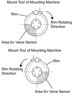
(d) Set the wheel disc to the mounting machine and install the lower tire bead. Position the main body of the valve sensor as in the shaded area shown in the illustration. NOTICE: If the valve sensor is positioned outside this area, it generates interference with the tire bead, causing possible damage to the valve sensor. |
|
(e) Install the upper bead.
NOTICE:
Make sure that the tire bead and tool do not interfere with the main body of the valve sensor and that the valve sensor is not clamped by the bead.
5. INSTALL FRONT WHEEL
Torque:
131 N·m {1,340 kgf·cm, 97ft·lbf}
6. INSTALL REAR WHEEL
Torque:
131 N·m {1,340 kgf·cm, 97ft·lbf}
7. INSPECT TIRE
(a)
Inspect the tire
.
8. REGISTER TRANSMITTER ID
(a)
Register the transmitter ID
.
9. INSPECT TIRE PRESSURE WARNING SYSTEM
(a)
Inspect the tire pressure warning system
.
10. PERFORM INITIALIZATION
(a)
Perform initialization
.
NOTICE:
Certain systems need to be initialized after disconnecting and reconnecting the cable from the negative (-) battery terminal.

|

|