| Last Modified: 4-30-2014 | 6.6 A | Doc ID: RM000001BLH002X |
| Model Year: 2006 | Model: LX470 | Prod Date Range: [05/2005 - ] |
| Title: ENGINE HOOD / DOOR: BACK DOOR: DISASSEMBLY; 2006 MY LX470 [05/2005 - ] | ||
DISASSEMBLY
1. DISCONNECT CABLE FROM NEGATIVE BATTERY TERMINAL
CAUTION:
Wait at least 90 seconds after disconnecting the cable from the negative (-) battery terminal to prevent airbag and seat belt pretensioner activation.
2. REMOVE ASSIST GRIP
(a) Using a screwdriver, remove the 2 assist grip plugs.
HINT:
Tape the screwdriver tip before use.
(b) Remove the 2 screws and assist grip.
3. REMOVE BACK DOOR INSIDE HANDLE BEZEL
|
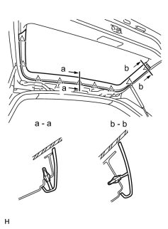
4. REMOVE CENTER BACK DOOR GARNISH (a) Using a screwdriver, remove the center back door garnish. HINT: Tape the screwdriver tip before use. |
|
|
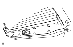
5. REMOVE BACK DOOR GARNISH (a) Using a screwdriver, remove the center back door garnish. HINT: Tape the screwdriver tip before use. |
|
|
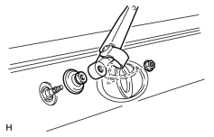
6. REMOVE REAR WIPER ARM (a) Open the cover. (b) Remove the nut and rear wiper arm. Torque: 5.4 N·m {55 kgf·cm, 48in·lbf} (c) Remove the grommet. |
|
|
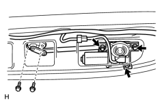
7. REMOVE REAR WIPER MOTOR AND LINK ASSEMBLY (a) Disconnect the connector. (b) Remove the 2 bolts. (c) Unfasten the 3 bolts and remove the rear wiper motor and link assembly. |
|
8. REMOVE REAR WIPER MOTOR RELAY
(a) Remove the bolt and rear wiper motor relay.
|
9. REMOVE BACK DOOR WEATHERSTRIP (a) Remove the back door weatherstrip. NOTICE: Do not pull strongly on the weatherstrip as it may tear. |
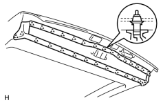
|
|
10. REMOVE BACK DOOR INSIDE HANDLE (a) Remove the 2 bolts. (b) Disconnect the back door lock locking rod and back door lock inside opening link, and then remove the back door inside handle. |
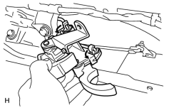
|
11. REMOVE BACK DOOR LOCK CONTROL ASSEMBLY
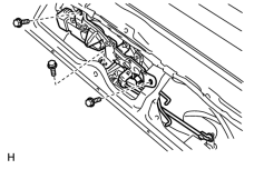
(a) Disconnect the links.
(b) Remove the 3 bolts.
Torque:
5.0 N·m {51 kgf·cm, 44in·lbf}
(c) Disconnect the connector, and then remove the back door control.
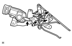
HINT:
At the time of reassembly, please refer to the following item. Apply MP grease to the sliding surface of the back door control.
12. REMOVE BACK DOOR OUTSIDE HANDLE
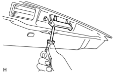
(a) Using a screwdriver, remove the back door outside handle.
HINT:
Tape the screwdriver tip before use.
|
(b) Remove the 3 bolts and back door outside handle assembly. Torque: 5.0 N·m {51 kgf·cm, 44in·lbf} |
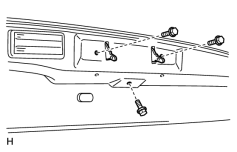
|
13. REMOVE LICENSE PLATE LIGHTS
14. REMOVE BACK DOOR LOCK ASSEMBLY
(a) Remove the 4 bolts and back door lock.
Torque:
7.0 N·m {71 kgf·cm, 62in·lbf}
15. REMOVE BACK DOOR LINK PROTECTOR
|
16. REMOVE REAR MAT SET PLATE (a) Remove the 5 screws. (b) Using a screwdriver, remove the rear mat set plate. HINT: Tape the screwdriver tip before use. |
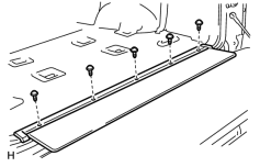
|
|
17. REMOVE BACK DOOR TRIM PANEL ASSEMBLY (a) Insert a screwdriver between the door and door trim to pry out. HINT: Tape the screwdriver tip before use. (b) Remove the back door trim. |
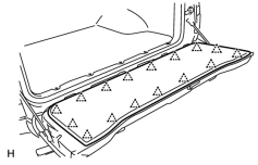
|
|
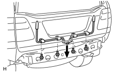
18. REMOVE BACK DOOR LOWER TORSION BAR ASSEMBLY (a)
Remove the rear bumper
(b) Remove the 4 bolts and lower torsion bar as shown in the illustration. (c) Remove the torsion bar guide. |
|
![2006 MY LX470 [05/2005 - ]; EXTERIOR: REAR BUMPER: REMOVAL](../../../../stylegraphics/info.gif "2006 MY LX470 [05/2005 - ]; EXTERIOR: REAR BUMPER: REMOVAL")
|
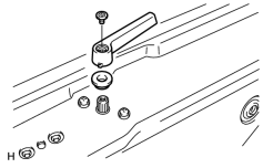
19. REMOVE BACK DOOR INSIDE HANDLE (a) Remove the screw and back door inside handle. (b) Remove the spacer. |
|
|
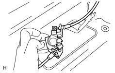
20. REMOVE BACK DOOR LOCK CONTROL ASSEMBLY (a) Remove the 2 screws. Torque: 5.0 N·m {51 kgf·cm, 44in·lbf} (b) Disconnect the back door lock control cables, and then remove the back door control. |
|
21. REMOVE SERVICE HOLE COVER
NOTICE:
Do not tear the service hole cover.
|
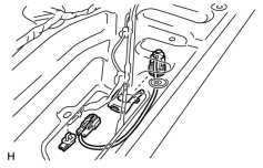
22. REMOVE BACK DOOR KEY CYLINDER (a) Disconnect the connector. (b) Remove the 2 bolts and key cylinder. Torque: 5.0 N·m {51 kgf·cm, 44in·lbf} |
|
23. REMOVE BACK DOOR LOCK
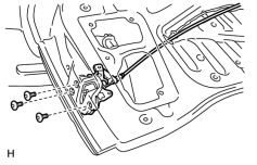
(a) Disconnect the control cable from the clamp.
(b) Using a "torx" wrench, remove the 3 screws and back door lock.
"Torx" wrench:
T30 (Part No. 09042-00010 or locally manufactured tool)
Torque:
5.0 N·m {51 kgf·cm, 44in·lbf}
HINT:
At the time of reassembly, please refer to the following item. Apply MP grease to the rotating parts of the door lock.
|
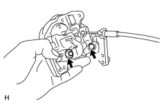
(c) Employ the same manner described above to the other side. |
|
|
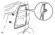
24. REMOVE REAR LIGHT ASSEMBLY (a) Disconnect the connector. (b) Remove the 2 nuts. (c) Using a screwdriver, remove the rear light. HINT: Tape the screwdriver tip before use. (d) Employ the same manner described above to the other side. |
|
|
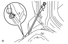
25. REMOVE TAIL GATE STAY SUB-ASSEMBLY (a) Using a "torx" wrench, remove the 2 screws and tail gate stay. "Torx" wrench: T 30 (Part No. 09042-00010 or locally manufactured tool) Torque: 18.5 N·m {189 kgf·cm, 14ft·lbf} (b) Employ the same manner described above to the other side. |
|

|

|